• The move to the new server is done. There are some software and database maintenance updates in process. This has us passing the hat around to help out. We appreciate any donations. Seriously, even a dollar helps. The payment page may be found here - https://www.audiokarma.org/support.html

Sansui Turntable - Particularly XR-Q11

Way over my head. I feel like the kid who can't read and is only looking at the pictures in a book
.
Way too cool that you are even looking at the pictures! Enjoy. And really, if you got any questions, please. Here's my story on "ask questions"...I'm a chemist, needed a job and stumbled into an electrical engineering job at Chrysler. Way out of my element and I'm at this review meeting. We're looking for stuff that runs into other stuff when the car moves. Haha, well I should have know someone needed to do it but now I guess it was me. And I don't know why you even need a degree to do that. And don't get me started on the 8 hours we spent trying to decide where to put the car jack.

So I have no idea what is going on. I stop the guy and ask a few questions. I find out none of the other engineers know what's going on either. They were afraid to stop and ask. I got quite popular...
 
+5V Power Supply

This is pretty simple, pump in +14 volts, the IC only let’s out +5V. It’s a voltage regulator. Unfortunately, to do this, it dumps voltage by consuming amps and producing heat. But, they’re a cheap way to get a regulated voltage.

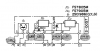
Here’s the Sansui one in the XR-Q11:
upload_2023-1-14_15-36-21.png
The +5V power regulator is on the left, the FS7805M, fed by a +14.3V line from the power supply.

The -5V power regulator is on the right, the FS7905M, fed by a -14.2V line from the power supply.

For the moment, we’ll ignore the -5V since the +5V is the only one used to power the Sensor E/F electronics. Interestingly, the +14.3V line that feeds the +5V supply has a couple of extra stages of filtering compared to the -14.2V feed for the -5V supply. But we’ll ignore, that, too, for the moment.

The FS78xx and FS79xx series are very likely the Mitsubishi version of the very popular 78xx and 79xx voltage regulators sold by a lot of different places. They appear to be dated [old, obsolete, well maybe not dead yet - what a surprise...], and there are better alternatives out there now.

What I did not realize, various manufacturers use different internal IC circuits to implement the voltage regulation. Here is a really interesting web page:
https://www.righto.com/2014/09/reverse-engineering-counterfeit-7805.html

Here’s a good voltage regulator design article:
https://www.electronics-notes.com/a...y-electronics/7805-7812-voltage-regulator.php

And another one, on an audio page.
https://sound-au.com/articles/vi-regulators.html

Apparently, the 7805 has no provision for handling a low voltage:
https://electronics.stackexchange.c...output-if-input-is-lower-than-5-volts-lets-sa

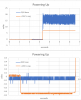
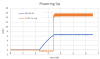
So again, here’s the actual data on start-up (power-up) on the turntable:
upload_2023-1-14_15-38-2.png

The big question still, is it the main power supply or other electrolytic caps that are bad or is this the normal start-up for this chip? Because it's burning out the tantalum caps... :mad:

Well, still looking on-line, let me know if any of you all have any thoughts...I'm not replacing anything till I am sure it's going to last another 40 years...
 
Last edited:
Just took a long walk with dogs to contemplate this. I think power-down is normal. I think the oscillation at startup is normal and probably not a problem. I want to keep digging for that. Somebody must have looked at this IC chip for transients at startup.

The negative voltage (-0.6V for ~1sec) is not good for the tantalum caps and may be a design problem. My initial bet, the big caps on the main power supply for the +14V are implicated. The 1 second time is a dead giveaway that this this might be a big cap charging). The caps may be somehow pulling the line negative while they charge up and this translates directly through the regulator, which is not designed to handle low or negative voltage. Next, though I probably need to take a look at the transistors that feed the +14V. And any of the caps that go directly to ground on the +5V line.
 
Oh yes, and if anyone has any tech info or a datasheet on the FS7805, please post it. There's plenty of LM7805 and look alike's on the web but as the above link proves, they can all be different internally. And I cannot find anything save a few other pieces of equipment that use this specific regulator.
 
Will be curious to see if the oscillation at power up on the +5V regulated supply can be corrected merely by replacing caps. Perhaps using a different variant (vendor) 7805 may be in order if the exhibited behavior is more pronounced on the Mitsubishi version.

Worst case scenario is that perhaps a time delay circuit with a solid state relay is needed to enable the +5V out only after it has stabilized post-power up. That would be an excessive work around, though.
 
14V Supply
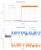
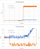
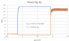
Measuring at main board interconnect pin 18 (14V into regulator) and pin 19 (+5V back from regulator)
upload_2023-1-14_19-9-20.png
upload_2023-1-14_19-9-48.png
upload_2023-1-14_19-10-23.png

So yes, the +14V supply is not thrillingly clean but, as the second plot shows, the +14V supply is also dipping below zero....
 
Promising to show you the good the bad and the ugly, I'm tracking down why is the initial voltage on power-up dipping negative. So I's hooking up the scope to this:
upload_2023-1-15_9-50-32.png
This is the +14V supply. Now, I think this is weird, they use a rectifier, not exactly a full wave rectifier but really, two half wave rectifiers, one to supply the +14V and one to supply the -14V. They have slightly different loadings because the +14V goes through some transistor buffers before the voltage regulator while the -14V goes straight to the voltage regulator. Maybe there is something circling back during a half cycle?

The ugly part, I want to monitor both sides of the 14V at the same time. I don't want the -14V to go downward on the scope. So I reverse the leads on channel 2. Ooops. Channel 1 and Channel 2 have a common ground (as well as the signal generator). So basically, I dead short the 14V supply with my cheapo oscilloscope.

Luckily, I test the scope, no problem. The turntable, however, won't power up. Luckily, they fused it. Two 0.5A fuses blown. Looks like a trip to Home Depot. Hopefully nothing else is harmed. Probably not, just wires between the test point and the power. No melted insulation. No smell of electrons wafting through the house. Near miss...

upload_2023-1-15_10-8-33.png
 
Last edited:
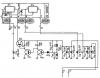
In the meantime, here's the +14V input to the regulator...in the above schematic, it is pin 11 from the power supply board. I was actually testing at pin 11 and 12 on the main board, which hook up to pin 10 and 11, respectively, on the power supply board...confusing, huh? This is the other part of the schematic:
upload_2023-1-15_10-15-52.png
I'll dump a lot of 'scope plots here and you can reference the test points above. Basically, I want to see what is happening at the transistor bases and the two diodes Dz8 and D8. Note these are different diodes with almost the same name (Sansui!).

In all of the plots, ch2 (orange) is pin 18, the +14V supply to the regulator from the string of transistors. Where does the negative voltage start that is eventually showing up at pin 18 to the regulator?
 
Last edited:
Going backward, Q34base
upload_2023-1-15_10-24-15.png
Nope!
Q33base:
upload_2023-1-15_10-25-13.png
Yep! Slight positive, probably inverted and amplified...
Q32base:
upload_2023-1-15_10-26-51.png
Nope.
Dz8cathode (the side we haven't looked at...)
upload_2023-1-15_10-28-5.png
Nope.
D8 junction with R144 (the side we haven't looked at...)
upload_2023-1-15_10-29-21.png

I mean, why did I do all this measuring? It'll probably be easier to figure out what they're doing than to try and analyze the circuits. :rflmao:

Or maybe just find where Waldo is, which appears to be Q33...:rflmao:
 
So the current state of affairs:

Why is there a negative voltage on the incoming +14V line at startup (and how not to blow up your scope or turntable while trying to figure this out) and

Why is it getting all the way through the filter/buffer transistors, through the regulator and to the tantalum caps, causing premature aging?
 
Oh no, I forgot the most important one.

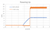
This is the +14V on pin 18 (orange) on the main board as it goes out to the regulator and the +14V at pin 11 on the main board as it come in from the rectifier. It is only going through Q34...
upload_2023-1-15_15-31-50.png

Oh yeah, good news, running all over, I found the fuses at my local hardware store. We're back in business.

So I think what we're looking at is something on the rectifier line is popping the +14V line to the more positive than +14V, that causes Q33base to go slightly positive for about 1 second which is inverted and amplified as an output to the voltage regulator. The voltage regulator does nothing to negative voltages except pass them right on through to the tantalum capacitors.

I want to take a look at the other half-wave rectifier, the -14V, and see if it maybe is pumping up the +14V during startup.
 
Last edited:
@Sansuiman your instincts were right when you were interested what things would look like when I changed the caps. I'm putting together a list but in the meantime, I put together an LTSpice simulation following this guys super video:

I'm no expert but I threw this in:
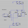
upload_2023-1-16_21-35-14.png
This is basically the power supply for the 14V lines.

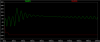
Here's the simulation of the startup for absolutely ideal caps the first couple of seconds on top, blown up to the first couple of milliseconds below.
upload_2023-1-16_21-37-19.png
upload_2023-1-16_21-37-28.png
Hope you can see that, but if you can't both negative (red) and positive (green) go up to voltage smoothly.
 

Attachments

  • upload_2023-1-16_21-36-59.png
    upload_2023-1-16_21-36-59.png
    26.5 KB · Views: 4
Now start to make the big caps non-ideal, adding in this case, inductance to the caps. Same, seconds on top, milliseconds below, zoomed in from the top:
upload_2023-1-16_21-40-56.png
upload_2023-1-16_21-41-10.png

OK not exactly what we're seeing but close enough that I think we got a winner.

The power supply caps get soft, outputting a funny waveform that leads to a voltage surge for 1-2 seconds on startup. This gets a really small -0.1mV signal in Q33 inverted and shoved through to the +5V voltage regulator which sends it through to the tantalum filter caps, reverse biasing them over and over for 1-2 seconds on every startup. Eventually, they give up and not longer provide the correct pulses for Sensor E & F to the computer.
 
This will take awhile...got to do the time-consuming part of finding the right replacements. At least I'm pretty sure now that this is not a fundamental design issue but rather a probably somewhat extensive aging problem. Maybe @Sansuiman I'll take you up on one of your suggestions or come up with another that will protect the tantalum caps, or even better, use better caps...
 
Last edited:
Updated list, still in process... 56 parts so far, mostly electrolytic capacitors.

the .txt file is tab delimited if you want to import into Excel...

This is the final (at least for now...) :music: while we wait for Digikey to get stuff here...

About $50 ...
 

Attachments

Last edited:
I've also been busy looking at the FR-D55 schematic. This is interesting, the FR-D55 is a lower end model that has the same track selection circuitry as the XR-Q11. But, I think it was released later than the Q11. One dead giveaway is the mask-ROM MPU for the XR-Q11 is a uPD546-150, the one for the FR-D55 is a uPD546C-181, a later number.

They cleaned up the schematic, it is much neater. There are also a number of smaller or larger changes. For instance, the LED sources for sensors A & B run more current (i.e. the engineers found they needed a little more light). There is a resistor eliminated that was, really, entirely superfluous. It was a 1M-ohm in parallel with a 22K-ohm...duh.

Oh yeah, looks like the +5V power supply was entirely redesigned!

On to desoldering and soldering soon...
 
Back
Top Bottom