• The move to the new server is done. There are some software and database maintenance updates in process. This has us passing the hat around to help out. We appreciate any donations. Seriously, even a dollar helps. The payment page may be found here - https://www.audiokarma.org/support.html

Scott LK-150 restoration thread

Alright so I decided to take a risk and power it up before the cans arrive from hayseed hamfest. I borrowed the tubes from various amps in my collection, turned the bias pots all the way down, hooked up some speakers and decided to give it a shot. Unfortunately when I powered it up and checked the bias the bias meter pegged out to the max setting and there was a small flash in one of the output tubes. I better wait until the replacement cans get here before I do any further testing. In the meantime is there anything else you guys think I should look into changing? Maybe some of the higher wattage resistors? Or should I just wait for the cans and see how it sounds before going any further? The good news is there were no blown fuses or smoke at power up so it's looking good so far!
 
So after studying the service bulletin and the assembly instructions I'm having trouble figuring out where some of the connections go. I under stand the pin numbers for the tube sockets and the pin numbers for the can caps (c1-c4) but what does it mean when it says things like connect to D1C, D2C, D1B, etc? It may just be my blurry assembly manual but I can't find anything labeled starting with a D anywhere on here
 
And the AK Database for the win once again! I tracked down an assembly sheet with clear labels and color pictures and have a better idea of how the modification works. Going to trace it out now and write my own steps to follow to make sure it's done right. I'll post a copy of my steps starting with what was undone and followed by me implementing the service mod in case it might help someone in the future.
 
Looks like I spoke too soon. It's making alot more sense but it looks like half of the service bulletin was already done. There's definitely a few steps missing but a few have already been done too. Probably just to accommodate the can caps being changed to 20/20/20/20 over the production cycle. The issue I'm running into now is how the pins are labeled for the can caps. I can't find a diagram in the closeups page I have that shows the pin numbers for the can caps. Once I have that I can follow along with the bulletin instructions vs the original assembly instructions and see what all has already been done. While going over this I have decided to go ahead and change all all of the resistors that are larger than 1/2w just for my own piece of mind since I'll be waiting for the hayseed caps either way
 
The issue I'm running into now is how the pins are labeled for the can caps.
The cap can sections are usually labeled with symbols, e.g., a triangle, a square, a crescent or half moon, and one left blank. The symbols can be seen on the underside of the cans, next to the terminals. (May need a magnifying glass and a good light source to get them in focus.) The labels on the cans, if they are still legible, will show each section’s capacitance and voltage rating.

Since you mentioned you might have cap cans made, I wonder if it might be worth having a look at the design of the power supply, and thinking about whether it could be revised with modern, higher capacity components, to accomplish the same thing but eliminate having a hot can shell? Cardboard sleeve or not, it just seems like a terrible idea to have this shock hazard sitting right there, front and center on an amp that I don’t think they even made a cabinet for(?). Just a thought . . .
 
Last edited:
I know how to read the cans and the labels are nice and clear but my problem is the service bulletin and assembly instructions that were implemented later in the amps production cycle are written like "connect wire from c4 pin 4 to c2 pin 5" I'm trying to determine which tabs on the actual cans correlate to which pins mentioned in the assembly instructions. As far as upping the capacitance I think I'll hold off until I hear this thing stock and then go from there
 
which instructions are you looking at? The link is just to a schematic, and it appears that each cap section has a unique number.
 
I know how to read the cans and the labels are nice and clear but my problem is the service bulletin and assembly instructions that were implemented later in the amps production cycle are written like "connect wire from c4 pin 4 to c2 pin 5" I'm trying to determine which tabs on the actual cans correlate to which pins mentioned in the assembly instructions. As far as upping the capacitance I think I'll hold off until I hear this thing stock and then go from there

Check the assembly manual in the database (specifically part 2), it shows the pin numbers for the capacitors.
 
The cans would only have hot cases if using CE / Mallory cans as sold by Antique Electronics.
Whether you restuff yourself or get from Hayseed (who stuffs new caps into new cans, iirc) you will not have voltage on your cases.

Honestly for the two small bias caps i would find a place underneath to mount a terminal strip, and leave the can in place for looks.

A couple other things I noticed from the schematic in the archives - the reservoir cap is actually two caps in series. This is a great way to handle high voltage but to do it with cans you can’t have a shared negative - it requires separate cans or separate caps. What I do for these is what Ampeg did on their bass amps, which is to make a long dynamite cap out of two axial caps in series, shrink wrap them and mount underneath. Extra points if you use balancing resistors. I do this on Dyna MKIII amps also. Anytime you have Very high voltage, as you do with this amp, its the way I go.

Then all thats left is a 40-20-20 can which I believe JJ makes.

Odd for me to see how they implemented two rectifiers. The plates on each one are tied together, and fed from one end of the HT winding. Pretty cool.
 
Sorry for the delayed response, had a pretty busy weekend. I've been using the assembly manual and the service bulletin to try to determine if it has already been done on my unit. I checked out the assembly manual part 2 and I'm still not seeing the can sections being individually numbered. I see some numbers but it doesn't make sense to me the way they've numbered the tabs. They appear random at first but when comparing to the assembly manual it looks like the numbers I'm seeing refer to how many connections should be on each tab before soldering the connection. When comparing my amp to the service bulletin and the assembly manual steps that are replaced with the service bulletin update it looks like it has been partially update. Most likely this unit was made after they swapped the can caps from a 30/30 to a 20/20/20/20 but before they came up with the rest of the update. So I have the correct size cap installed but there are around 3 or 4 resistors that are the wrong size. I just need to determine if all the connections are in the right place or not before I change these resistors

On the can caps, I went ahead and ordered the hayseed caps to avoid the headache of restuffing. Just gtta wait for them to get here then I can finish up this job.

 
Sorry for the delayed response, had a pretty busy weekend. I've been using the assembly manual and the service bulletin to try to determine if it has already been done on my unit. I checked out the assembly manual part 2 and I'm still not seeing the can sections being individually numbered. I see some numbers but it doesn't make sense to me the way they've numbered the tabs. They appear random at first but when comparing to the assembly manual it looks like the numbers I'm seeing refer to how many connections should be on each tab before soldering the connection. When comparing my amp to the service bulletin and the assembly manual steps that are replaced with the service bulletin update it looks like it has been partially update. Most likely this unit was made after they swapped the can caps from a 30/30 to a 20/20/20/20 but before they came up with the rest of the update. So I have the correct size cap installed but there are around 3 or 4 resistors that are the wrong size. I just need to determine if all the connections are in the right place or not before I change these resistors

On the can caps, I went ahead and ordered the hayseed caps to avoid the headache of restuffing. Just gtta wait for them to get here then I can finish up this job.
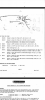
My apologies, I think I directed you to part 2 of the assembly manual but what you probably need is this image from the "close ups" file:

Screenshot_20221108-231923_Adobe Acrobat.jpg

Note that the 20-20-20-20 can has the same thing at each of the 4 pins, so as long as you're not confusing ground lugs with cap tabs you should be ok, and as long as you're consistent with, for example, whatever connections are meant to be made at pin 2 of that cap. Double check with the schematic to make sure that things that are supposed to go to cap tabs go to cap tabs and things that are supposed to go to ground lugs go to ground lugs.
 
Last edited:
That makes sense and is where my line of thinking was when I first tried to verify how much of the mod had been done. I'll sit down with the amp in an hr or 2 and see what I can come up with
 
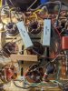
Alright so after following all the instructions again and making note of the pins numbers for each can cap it looks like the entire mod has been completed EXCEPT the last 3 steps where the resistor is changed. Screenshot_20221109-123112.png
 
If I'm following this correctly, then the resistors on the far right of each bias pot need to be removed and replaced and I need to replace the 220ohm resistor on C1 with a 6.8k resistor. Besides those last few steps everything else has already been done it looks like
 
Does anyone here have an LK-150 that doesn't mind posting a picture of the connections on their can caps so I can compare to mine and make sure there's no mistakes?
 
Actually, I think I may be mistaken. The update doesn't say anything about removing that resistor and I think it's on different pins. The instructions say to connect a 6.8k resistor (they suggest a 22k and 10k resistor combined due to parts availability) from pin 2 c1 to pin 5 c1.
 
It looks to me like the 220 ohm resistor is going from pin2 to pin4. So I should then add the 6.8k from pin 2 to pin 5 (I believe this is the ground lug)? Sound like I'm on the right track?
 
I went ahead and ordered the 6.8k resistor from mouser and also decided to go ahead and replace all of the resistors that are over 1/2w while I'm in there. Figure they see more voltage so are more likely to fail or drift. I'll update here once I get those parts in and the caps from hayseed. Any other suggestions for things I should do here? Would the yellow sheet diode mod be worth pursuing in this case since the amp uses a rectifier tubes? Any other safety or longevity mods I should look into?
 
Back
Top Bottom