
• The move to the new server is done. There are some software and database maintenance updates in process. This has us passing the hat around to help out. We appreciate any donations. Seriously, even a dollar helps. The payment page may be found here - https://www.audiokarma.org/support.html

Scott LK-48-B Bias Voltage Help

njcanuck

aka: MacGyver
Hey guys. The restore of my 299 went so well, I decided to tackle my LK-48-B. Of course I hit a hitch right away: I can’t seem to get low enough bias voltage to pin 2 of the 7189s.

First I installed 10Ω cathode resistors and test jacks so that I could easily see how the tubes were biased. To do this, I replaced the common 10Ω 2W resistor on pin 3 of each channel with 2 10Ω 1/4W resistors and clipped the leads to the old bias switch. I immediately noticed that the highest possible bias voltage across the sensing resistors was only about 0.11V (I was expecting 0.20V and higher).

So I went ahead and replaced the selenium rectifier, dropping resistor (put in a 33Ω 5W) and the 100uF bias caps. At 117V input, this gives me -58.1V after the bridge, -44.7 at the first 12AX7 and -48.7V up to the bias pots. However, the lowest that I can dial the pin 2 voltage is -16.5V resulting in only 0.11mA current draw per tube. If my understanding is correct, I want approx 0.23mA draw and need -15V or less to get there. Right?

I’ve attached the relevant part of the schematic with my changes in red and the voltages in blue. I can see two possible approaches to lower the -16.5V at pin 2: a) raise the value of the 10K resistor (R211) to lower the voltage up to the bias pots, or b) lower the value of the bias-pots-to-ground 150K resistor (R214) that I believe will lower the bottom end of the pin 2 range.

Or is there something else going on here? Did I mention that I’m pretty new at this. :D

Any advice will be much appreciated!

Edit: corrected schematic
 

Attachments
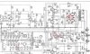
  • LK-48-B Schematic AK.jpg
    LK-48-B Schematic AK.jpg
    109.9 KB · Views: 69
Last edited:
Register to hide this ad
Both approaches will work to lower the bias voltage, each with slightly different results however. Chose the one that works best for you:

1. If you raise the value of the 10K dropping resistor, it will lower the bias voltage, and in doing so, also reduce the range of bias voltage available from the bias control that is applied to the balance control.

2. If you lower the value of the 150K resistor at the bottom of the bias controls, it will lower the bias voltage, and in doing so, also increase the range of bias voltage available from the bias control.

If the controls are overly sensitive to the touch, then #1 would be the best way to go. On the other hand, if more control range could be used, then #2 would be your choice.

Good luck with it!

Dave
 
Have you replaced the coupling caps yet?,is the bias cap polarity correct,pos to the chassis?
 
Last edited:
Thanks Dave - I think I might be getting the hang of this!

S-P: Bias cap is correct polarity (and the voltage was off before I replaced it). Haven't done the coupling caps yet thinking that I should try to get the bias voltage between -12V and -15V first. I might lift a leg on a couple tonight and check them anyway. I haven't purchased replacements, yet.
 
Leaky coupling caps would tend to drive the bias voltage more positive than it ought to be. Leaky or gassy tubes would tend to do this too though, so you might want to plug those things into a tester to make sure you're not fighting dead tubes. I seriously doubt all four would be similarly bad though.
 
I tried two different quads of tubes (Russian 6P14Ps). One set was tested and known good. Same result with all.
 
Actually one of the 18 ohm resistors to the filaments may have changed value,the bias is high and the filaments are low,so some resistor in the middle likely changed.If you measure across the resistors,the voltage across each of them should be the same.
 
Last edited:
The 18 ohm resistors all measure 19 or 20. There are only two resistors between the bridge and the bias pots - the 33 ohm 5w and the 10k 1/2w. I'm getting -48.7V up to the bias pots where the schematic calls for -48V so I think those resistors must be ok? If there is a resistance problem wouldn't it be after the bias pots? Is it possible that the removal of the original bias switch from the circuit is having an effect?
 
At 20 ohms,it is out of tolerance,10%? correct? I realize the voltage is only a little high at the pot,but the filament voltage is a little low.it is still possible other resistors around the bias pot are out of tolerance also.The down stream resistors will pull the upstream bias resistor lower.It may only pull it down a couple of volts
 
Last edited:
Depends which Russian variant. The 6P14P-EV should be perfectly happy with 400v. The regular 6P14P is rated for 300-400v per the datasheets, The -V and -EV are listed as 300-500v on the plate.
 
Thanks for the reassurance on the bias switch.

Point taken on the 18s being out of tolerance and I see how they affect the 12AX7 filaments but not how they affect the bias voltage to the output tubes. (Not trying to be argumentative - just trying to understand).

Good point on the possibility of other resistors having drifted so I lifted some legs on one output tube and checked them as well as the coupling cap. All resistors were within 5% and the cap was 9% under. The 150k bias pot resistor had drifted up to 163k, 8.7% off.

I subbed in a 100k for the 150k which brought the pin 2 bias voltage down to -15.5V (still not low enough). So I paralleled in another 100k to get 50k. This gave me a voltage range of -12.3V to -18.5V and the outputs biased nicely (.23mA) at -14.5V.

It works but it doesn't really smell right. I guess I'm uncomfortable that the 150k needs to be dropped to 50k to make it work. Could this be a symptom of something else being out-of-whack?
 
I'm running regular 6P14Ps (not EVs) cause that's what I got at the moment. My understanding is that they should work ok at 400 B+ but probably won't last as long.

I am using a variac to set the input voltage to 117.
 
The reason that the 18's make a difference is the resistors form a dividing network starting with the 30 ohm, to ground through the filaments.so you have 30 18 18 18 to ground through the filaments.The lower the resistance of the 18's the closer to ground the bias voltage will be,but it will raise the filament voltage. if you pull one of the tubes in that series your bias will go high.
 
Another thing to check is the screen grid voltage (pin #9) on the output tubes. If this voltage is lower than expectation, then the required negative bias voltage will also need to be reduced (possibly to less than is available within the range of the bias control as designed) to achieve a given current draw through the output tubes.

Also, be sure the check the 330K and 390K resistors in the DC balance circuit. These resistors form a voltage divider to help reduce the bias voltage to the correct value. If (for example) the 330K resistors have drifted high, that will increase the bias delivered to the output tube grids -- again, possibly throwing the the ability to correctly bias the output stage outside the range of the bias control.

Keep us posted, but I'm sure you'll figure it out soon!

Dave
 
I have a question,Where does the spec for bias current come from?If you are using it from the Scott before you modified the cathode resistor,you currently have 1/2 the resistance that you had before,before 10ohm per pair,
now the equivalent of 5 ohm per pair.
 
The reason that the 18's make a difference is the resistors form a dividing network starting with the 30 ohm, to ground through the filaments.so you have 30 18 18 18 to ground through the filaments.The lower the resistance of the 18's the closer to ground the bias voltage will be,but it will raise the filament voltage. if you pull one of the tubes in that series your bias will go high.

Just a mention though, resistors seldom drift low in value. I've actually never seen it. Not to say its impossible, but the typical failure mode is high value with carbon comps.
 
Back
Top Bottom