• The move to the new server is done. There are some software and database maintenance updates in process. This has us passing the hat around to help out. We appreciate any donations. Seriously, even a dollar helps. The payment page may be found here - https://www.audiokarma.org/support.html

Sencore SG165 - AM/FM Analyzer - Repair

I was wondering if I should just use radial for the bi-polar caps. I'm almost done building the order list at Mouser. Thanks again!

The old six of one conundrum. :dunno:. If you are placing a Mouser order then make it simple and use the radials, one less order to place and saves an extra shipping charge.

With the terminal strips it should work out fine.

It is getting harder and harder to find the axial caps for general electronics use, polarized or not.
 
Order is in, should all be here this Thursday.

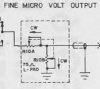
I'll spend the next couple of days pulling this apart, need to figure out why the fine Microvolt pot only works on the last 10%, it fell, or something was dropped on it, judging by the cracked knob.

Thanks again mrk229!
 
I was the person who started bidding on this on Ebay 5 minutes before the end and you beat me... I did buy a unit from someone I met at a local HamFest last week. Mine wasn't completely working and I recapped it this week and I think it is mostly working. I used all radial capacitors, I used Nichicon for the electrolytic capacitors, UPW and UPJ for the power supply, and UKL for the rest. I replaced the 2uF with 2.2uF Kemet film and they all went in easily. However, when I started calibrating 10.7mHz IF you need to connect a voltmeter to C303 and it was flush to the board. Today I ordered a couple of Axial Illinois Capacitor Manufacturer Product Number 225MWR050K. I also ordered a RF multimeter probe for some of the other calibrations. There bunch of components not listed in the parts list, does anyone know of the resistors not mentioned are 1/4? Sorry for making you pay more, but good luck on your restoration.
 
I never bid until the last 20 seconds, and then I'm all in :naughty:. The bid I put in was more than it finished at, no harm, no foul :thumbsup:. I'm redoing this one in all axial caps.

Vishay for the 2uF - for the PSU to start:
https://www.mouser.com/ProductDetail/vishay/tva1301-e3/?qs=7/EGLSFhKGQGKhN4sGf01g==

I won't be replacing any of the resistors unless they are CC.

Cool name BTW, a friend had Long Nose Gar's and Archers in a brackish tank, the Archers would spit too.
 
If those big electrolytic caps are in line with the speaker inputs, they were added to prevent power amps with high (positive) DC offset from destroying the SG-165. Notice that they are polarized, so that if the offset is opposite the capacitor polarity, bad things happen.
Since the SG-165 was designed primarily for automotive use, and radios and car stereos ran directly off of 12V 'back in the day' negative offset was not a big issue.

When I begin work on a receiver or amp, the first things I do are:
1. Visually check the fuse for value and condition.
2. Check for AC line to chassis leakage.
3. Check for DC offset at the speaker terminals, NEVER rely on the speaker protection circuit, I have found it bypassed in many creative ways.

Tom
 
Parts just arrived:
8ZfpinD.jpg


Time to get the PSU rebuilt. I did get the non-polar axial 1000uF from NTE, those aren't here yet, but I did get the radials from Mouser to test in that location, if I need to.
 
Stock 2uF caps:
Gby7YFF.jpg


New 2uF much closer in spec:
npK1ti1.jpg


Rebuilt:
2DPcCNR.jpg


JbGn50y.jpg


ZmQYowV.jpg


12.93V-, is a bit higher, will adjust to match 12.66V+
G3PoQn0.jpg


The FM RF output waveform is cleaner throughout the entire band. Still seems to be something going on with the Fine Microvolt pot.
 
Stock 2uF caps:
Gby7YFF.jpg


New 2uF much closer in spec:
npK1ti1.jpg


Rebuilt:
2DPcCNR.jpg


JbGn50y.jpg


ZmQYowV.jpg


12.93V-, is a bit higher, will adjust to match 12.66V+
G3PoQn0.jpg


The FM RF output waveform is cleaner throughout the entire band. Still seems to be something going on with the Fine Microvolt pot.

Way to keep plugging away. That fine adjust is not a pot. It is a 75 ohm L pad. Think of it as two pots inside a single case.

pad1.jpg


Not sure how easy it might be to find one. A lot of times you can carefully remove the lid (bendy tabs) and clean the guts.

The ones I have seen that look like a single pot have two tracks one inside the other.

pad2.jpg


Speaker L pads are wire-wound tracks and the wires and wipers oxidize.
 
Last edited:
Took it entirely apart:
NE7tLPe.jpg


Looks like the Coarse Microvolt is an L-Pad, but the Fine one on the right, looks like two stacked pots:
kcZ5IQA.jpg
 
Took it entirely apart:
NE7tLPe.jpg


Looks like the Coarse Microvolt is an L-Pad, but the Fine one on the right, looks like two stacked pots:
kcZ5IQA.jpg

The coarse one is a switched attenuator. The fine one is two single pots connected as an L pad. you might be able to clean it up with deoxit, if you can get it inside. Can't really tell from the pictures if the case has any openings.
 
Here's the mat I'm using:
https://www.amazon.com/gp/product/B0027RN0JW

I put my meter in continuity mode, and hooked it up to the Fine - L pad. I do see that when in full CCW position, it starts at about 85 ohms, then creeps up to about 140ohms as it goes CW, when it hits about 9 / 10 on the dial, the resistance then starts going back down sporadically, until full CW is 0 ohms:

 
I don't think the L pad is the cause of the FM output being dead, just one more problem. I've read FM output is usually caused by a blown FET. Will need to follow up with that.
 
By separating the two parallel and series rheostats' grounds, I was able to test each side of the L pad individually. I was able to determine it's the back half of the L pad, that has the dead spot.

This particular L pad was able to have the case removed:
FGtfKuo.jpg


1TdojcL.jpg


I may be able to fix this yet.
 
I tried to clean the rear half of the L pad, it has a dead spot that can't be fixed:
7Vo1cNG.jpg


In the xraytonyb video, he says he used a standard long shaft 100 ohm pot, is what he calls it. It doesn't even look to be an L pad.

At 9:40, he describes the "pot" he used:

He says it works perfectly. I can't understand how he used a normal pot in place of an L pad. Can anyone explain this?
 
Could I make the proper replacement out of a 10K ohm, with resistors to bring it in to spec:
10K OHM DUAL 2 WATT LINEAR CLAROSTAT POTENTIOMETER LONG SHAFT NOS 1 PCS.

s-l1600.jpg


Or just use a 100 ohm pot, with a resistor like xraytonyb said he did:
100 Ohm 5 Watt Wire Wound, Long Shaft Potentiometer - Centralab WW101
s-l500.jpg
 
I went ahead and ordered the 100 ohm pot above, and also a long shaft Mallory 75 ohm.

Also ordered all replacement transistors:
(MPF102 = NTE451) TR316, 308, 312, 313
(SE3002 = NTE108-1) TR301, 302, 303, 314, 315
(2N5227 =NTE159) TR310, 318, 322
(2n5172 = NTE289A) TR304, 306, 307, 323, 324
(MSP5172 = NTE123AP) TR320, 321

NTE451 back ordered for 8 days, nothing ships until it does. Will return to this project, soon.
 
Back
Top Bottom