

You are using an out of date browser. It may not display this or other websites correctly.
You should upgrade or use an alternative browser.
You should upgrade or use an alternative browser.
Sencore SG165 - AM/FM Analyzer - Repair
- Thread starter MarantzRefrb
- Start date

MarantzRefrb
Super Member
Thanks! I hadn't heard that the probes would cause any problems (especially with the law), they're a pretty simple circuit, and are being reproduced on eBay right now. If you search Sencore SG165 on eBay, the repro probe kit should be the first thing that comes up.
This SG165 being so complete, is was what made me buy it, despite the seller disclosing the entire FM RF was blown out.
This SG165 being so complete, is was what made me buy it, despite the seller disclosing the entire FM RF was blown out.

Ragwire
Member
That's cool. I wish they were available back when I got my unit. I had to build mine. Glad the schematic shows the probes, too. That 20uF in the balanced/unbalanced signal probe is apparently a typo though. I can't remember what the consensus was as to what value it actually is, but I used 2uF in mine and it works well.
Rob
Rob

DConley
New Member
I got a Sencore SG-165 off of Ebay with all probes, including an extra auto adapter (39G53). (I guess I am going to jail. LOL). After doing a lot of internet searches, I did a complete deoxit, re-cap, de-grease and re-greased ball bearings, replaced all 3 connectors in lower left with new BNC connectors, added left and right channel speaker inputs next to their analog meters, and finally a re-calibration. I only ran into two issues.
First issue, the slug in L305 was frozen, so I was not able to adjust the Marker Frequency (Service Manual pg 41) on the RF board to 100KHz. It is currently frozen at 101.88KHz. I tried to lookup the specs on L305 so I could order a replacement, but all it said was “Coil, 100Khz, 67Khz, Adj”. Any suggestions for a replacement part, or a “Liquid Wrench” type solution for loosening a stuck core. Like maybe hit it with Deoxit? – Or is +2% good enough?
The second issue, I do not have a “calibrated FM deviation meter” to calibrate the Modulation Percentage. My oscilloscope definitely reacted to each Left and Right 400Hz switches. Considering everything else was close to specs, I am assuming this is also working, and called it a day.
Notes for others: My Sencore SG165 was “Run 15”, and some of the caps were marked from 1977. I might have had couple of 1978s..
Only one capacitor in the entire unit was still within specs (+/- 20%, ESR)
The silk screen on the Power Supply board had the incorrect polarity for capacitors C104 (C4) and C107 (C7), as mentioned previously in this thread and by others.
A large number of the factory installed “2uF” capacitors were actually 2.2uF.
I used Nichicon UKL for general caps, UES (Muse) for bi-polar, and UPJ for power supply. I had to convert the latter two series into axial caps by soldering an insulated wire to one lead and folding it back over the cap and taping in into place with scotch tape. It worked quite well and was very stable.
The petroleum based grease in the ball bearings had started to solidify. I did a fairly good job of blowing out the old grease with CRC QD Electronic Cleaner. Replace the grease with white lithium web grease. Now, everything moves smooth and easy.
10.7MHz Sweep Phase (pg 41) Calibration: Pin 2 and 3 are shown on Fig 74 – “Feedthrough Test Points (Main RF number)” page 59, as pins A2 and A3.
We don’t have many strong local radio stations. However, I was able to align the AM RF, 455KHz, 262.5KHz, and FM RF using the oscilloscope to read the output frequencies and signal levels.
Thanks in advance,
David
First issue, the slug in L305 was frozen, so I was not able to adjust the Marker Frequency (Service Manual pg 41) on the RF board to 100KHz. It is currently frozen at 101.88KHz. I tried to lookup the specs on L305 so I could order a replacement, but all it said was “Coil, 100Khz, 67Khz, Adj”. Any suggestions for a replacement part, or a “Liquid Wrench” type solution for loosening a stuck core. Like maybe hit it with Deoxit? – Or is +2% good enough?
The second issue, I do not have a “calibrated FM deviation meter” to calibrate the Modulation Percentage. My oscilloscope definitely reacted to each Left and Right 400Hz switches. Considering everything else was close to specs, I am assuming this is also working, and called it a day.
Notes for others: My Sencore SG165 was “Run 15”, and some of the caps were marked from 1977. I might have had couple of 1978s..
Only one capacitor in the entire unit was still within specs (+/- 20%, ESR)
The silk screen on the Power Supply board had the incorrect polarity for capacitors C104 (C4) and C107 (C7), as mentioned previously in this thread and by others.
A large number of the factory installed “2uF” capacitors were actually 2.2uF.
I used Nichicon UKL for general caps, UES (Muse) for bi-polar, and UPJ for power supply. I had to convert the latter two series into axial caps by soldering an insulated wire to one lead and folding it back over the cap and taping in into place with scotch tape. It worked quite well and was very stable.
The petroleum based grease in the ball bearings had started to solidify. I did a fairly good job of blowing out the old grease with CRC QD Electronic Cleaner. Replace the grease with white lithium web grease. Now, everything moves smooth and easy.
10.7MHz Sweep Phase (pg 41) Calibration: Pin 2 and 3 are shown on Fig 74 – “Feedthrough Test Points (Main RF number)” page 59, as pins A2 and A3.
We don’t have many strong local radio stations. However, I was able to align the AM RF, 455KHz, 262.5KHz, and FM RF using the oscilloscope to read the output frequencies and signal levels.
Thanks in advance,
David
DConley
New Member
Update: I have done a lot of research since the last post.
First, I noticed on the schematics that inductor L305 is a 2mH inductor. Also, inductor L307 uses the same 2mH inductor. L305 is for the 100KHz marker, and L307 is for SCA 67KHz.
Second, I was measuring the physical size of L305 which is 3 pins on 3/8” diameter circle with the two wired pins opposite each other and a third (?)stabilizing pin 30 degrees to the right side looking down in plan view. That is when I noticed the ferrite slug was cracked, and that the inductor had been previously removed from the PCB. I guess I now know why.
Third, I did a lot of research on finding a suitable replacement. I ran into a rabbit hole with way more questions than answers about Q factor, and a lack of new 2mH inductors, …
Finally, I decided to look at what the 100KHz circuit was for. I think it just flanks both sides of the 10.7MHz signal at 10.6 & 10.8MHz. I think I could live with it being off by 2%, unless someone else has a better solution.
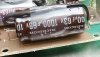
I also included a picture of the modification I did to convert common Radial Capacitors to Axial Capacitor.
Correction on the Run number, mine is Run 20.
Thanks!!
First, I noticed on the schematics that inductor L305 is a 2mH inductor. Also, inductor L307 uses the same 2mH inductor. L305 is for the 100KHz marker, and L307 is for SCA 67KHz.
Second, I was measuring the physical size of L305 which is 3 pins on 3/8” diameter circle with the two wired pins opposite each other and a third (?)stabilizing pin 30 degrees to the right side looking down in plan view. That is when I noticed the ferrite slug was cracked, and that the inductor had been previously removed from the PCB. I guess I now know why.
Third, I did a lot of research on finding a suitable replacement. I ran into a rabbit hole with way more questions than answers about Q factor, and a lack of new 2mH inductors, …
Finally, I decided to look at what the 100KHz circuit was for. I think it just flanks both sides of the 10.7MHz signal at 10.6 & 10.8MHz. I think I could live with it being off by 2%, unless someone else has a better solution.
I also included a picture of the modification I did to convert common Radial Capacitors to Axial Capacitor.
Correction on the Run number, mine is Run 20.
Thanks!!
Last edited:
Sencore SG165
7-4-21
no 400 hz signal on fm
pins 10 and 11 of SW301E; pin 11 is direct output square wave and works fine
as does pin 10 which is a sine wave check C220 and
C221
then pin 14 of RF
page 48 delineates such
as does figure 65 and 66
check for sine wave at CR207 and CR209
Step one confirm the dysfunction; confirmed all outputs are dead for MPX.
Hurrah there is a figure for both the MPX component side and foil side on page 56.
CR207 and CR209 are flat line! Wow C220 and C221 are flat line also. 12 volts goes into the audio oscillator via red wire on molex labeled A. Grey (IC2 output) and blue/white (diode buffered output) have 25 volts peak to peak sine wave output!
Back to MPX board signal is lost before pin 4y. Power down and trace such. 19 megohms in between pin 4y and blue/white wire output. R102 should be 4700 ohms and is 5100 ohms; within 8.5 percent so no biggie. Obviously we must bypass the 19 megohm or the infinity ohm connection with a white 24 gauge wire. Warming up the soldering iron as I type. Soldered in and connections verified! We do have waveforms on all the MPX settings now!
7-4-21
no 400 hz signal on fm
pins 10 and 11 of SW301E; pin 11 is direct output square wave and works fine
as does pin 10 which is a sine wave check C220 and
C221
then pin 14 of RF
page 48 delineates such
as does figure 65 and 66
check for sine wave at CR207 and CR209
Step one confirm the dysfunction; confirmed all outputs are dead for MPX.
Hurrah there is a figure for both the MPX component side and foil side on page 56.
CR207 and CR209 are flat line! Wow C220 and C221 are flat line also. 12 volts goes into the audio oscillator via red wire on molex labeled A. Grey (IC2 output) and blue/white (diode buffered output) have 25 volts peak to peak sine wave output!
Back to MPX board signal is lost before pin 4y. Power down and trace such. 19 megohms in between pin 4y and blue/white wire output. R102 should be 4700 ohms and is 5100 ohms; within 8.5 percent so no biggie. Obviously we must bypass the 19 megohm or the infinity ohm connection with a white 24 gauge wire. Warming up the soldering iron as I type. Soldered in and connections verified! We do have waveforms on all the MPX settings now!

I opened up my SG165 to check things out. the fine micro volt adjust pot was always wonky. Someone soldered an extension onto a 100Ω pot. They also put a .008µ cap at the output. Do you all think I should leave it there? All of the adapters look like they also have decoupling caps.
Tony
Tony

rkeller
Member
Mine SG165 is a run 17 and both C104 and C107/are marked (silkscreened) backwards as well. It prevented me from getting any variable RF output until replaced correctly. Schematic is correct but there is a mystery R108 that’s between the C104 (-) and R100 that doesn’t show up on the schematic.Mine is a run19. C104 and C107 were both marked backward.
Tony
OK I also have a Sencore SG165. When set to MPX and with both channels with 400hz at 88MC I get the 400 hz signal but there are about 14 undulations within the 400 hz signal. Please see the attachment which only displays 1/2 the cycle unfortunately, but the photo was taken in a dark environment. The output is from the L and R speaker outputs from a Pioneer SX534, Please help!![IMG_4520[1].JPG](/forums/data/attachments/2346/2346710-b5ee6d7f2ee6c36a85e1ffb45f2565ab.jpg?hash=te5tfy7mw2 "IMG_4520[1].JPG")
KentTeffeteller
Gimpus Stereophilus!
Nice job on getting this classic back to life and working well again.
Why thank you Kent! So with the Sencore SG165, I am now open for business for alignments.Nice job on getting this classic back to life and working well again.
Resume
In high school took electricity for one year with a gifted Navy radioman, what an excellent teacher
In high school took electronics for one year with that same gifted Navy radioman, still an excellent teacher, very lucky to have him
Had the opportunity to get a class D radiotelephone license, do not know if it is current
Completed a bachelors in bioengineering at the University of Illinois wonderful teachers here
Worked at Motorola as an intern in the crystals division in Schaumburg IL
In my fifties worked on four NRI tube radios starting with AM alignments using a 455Hz sine wave generator made by Knight kit
In my middle fifties to early 60s worked on many tuners;
Adcom GFT-2 4 electrolytic replaced on 6-6-15; replaced fuse with ¼ amp slow blow SB
Adcom GFT-555
Adcom GFT-555
Carver TX11
Dynaco AF6
Dynaco FM3 aligned on 11-4-20 stereophile class B has PEC upgrades and 4 capacitor
upgrades uses diode matrix and LC IF
Dynaco FM3 aligned on 11-7-20 stereophile class B has PEC upgrades and 4 capacitor
upgrades uses diode matrix and LC IF
Dynaco FM3
Dynaco FM5 modified chip MPX
Dynaco FM5 stock
Kenwood KT5500 stock new light bulbs times 3
Kenwood KT5500 stock new light bulbs times 1 wired in series!
Kenwood KT7500 bulbs, OPA2604, AD823, then OPA627BP, polypropylenes Schottkeys, bypassed 75us switch
Knight KG795 has 4 gangs and LCIF and diode matrix MPX
KLH 18 WB uses diode matrix and LC IF stereophile class B
KLH 18 WB uses diode matrix and LC IF stereophile class B
Needed meter surgery and meter face is upside down, gluing veneer
Mcintosh MR71 needed MPX work (lots) and silicon rectifiers and 6BM4A stereophile class A uses diode matrix and LC IF
Optonica ST3636 5 gang tuner
Philips AH6731 needed adjustment of center tune meter number 7 on fm tuner info
LC IF but chip MPX
Pioneer TX8100 aligned in 2008 WB black cabinet
Pioneer TX9100 modified polypropylenes WB swap cabinet; now walnut cabinet
Pioneer TX9800 feet replaced modified with Schottkys and 2 polypropylenes SB
Pioneer TX-9500 stock WB
Revox B760 needed a transistor and capacitor for power supply, meter transplant, alignment, 3 watt lamp, 4 24 volt lamps, 2 CA3053 can ICs, ceramic cap,
painted grey, toggle switch repair LCIF chip MPX number 8 on fm tuner info
Sansui TU-555 WB uses diode matrix and LC IF
Sansui TU-317 just moved tuning cap a little and it unseized
Sansui TU-517 highly modified with polypropylenes and Schottkeys
Sansui TU-717 modified polypropylenes 90 v Schottkys
Sansui TU-717 stock repaired with zener diode
Sansui TU-717 stock with hazy plastic two new transistors bad EC junction in small signal transistor
Scott LT112B broadcast monitor tuner sleeper uses diode matrix and LC IF
Scott LT112B broadcast monitor tuner sleeper uses diode matrix and LC IF
Tivoli Audio Model Two Stereophile class D 2007
Tivoli Audio Model One Stereophile class D 2014
In 2020 bought 10 tube tuners and 3 transistor tuners from facebook marketplace fixed them up and sold all but the venerable Scott LT112B because that is a great keeper tuner
So give me your tuners to work on for alignments! with bad RF sections, bad IF sections, bad discriminators, bad MPX sections, bad audio sections. I have a Sencore SG165 signal generator for MPX alignments, a Tektronix 150mhz four channel scope, several other Knight and Eico signal generators, Radioshack and B and K frequency counters, Sencore cricket transistor testers, RCA senior voltohmyst VTVM for discriminator alignments, Fluke multimeters. B and K capacitance meter, Tiny SA spectrum analyzer. I just enjoy this as a hobby and will help others on Audiokarma, now that I may be qualified.
Aha, now I have the schematic for the Sencore SG165 matching pad, and this matching pad is indeed missing, but I do have two detector probes. Cannot wait to see the improved waveforms with the proper matching pad! Will try a home brew build with 4 resistors, and two capacitors! I am so excited for this new project.

That manual is still out there, in case you hadn't saved it already.
http://www.wwdsltd.com/files/SencoreSG165OperationManual.pdf
http://www.wwdsltd.com/files/SencoreSG165OperationManual.pdf
Well the service manual for the Sencore SG165 is terrific, and I built a probe, the famous 39G43, and that did the trick. The waveforms at 88Mhz on the FM dial going through the MPX circuit and out the speakers show the 400hz sinewave on both the L and R channels. But you have to be a photographer to show it. The Canon Powershot A560 set to night view shows the 400Hz sinewave but the background is a little blurry.
Attachments
![IMG_4535[1].JPG](/forums/data/attachments/2347/2347731-3d26122f076f5931baa38dafb2b087e5.jpg?hash=PSYSLwdvWT)
![IMG_4537[1].JPG](/forums/data/attachments/2347/2347732-f9020d80c31c45b2324f6f9a3c62ce8b.jpg?hash=-QINgMMcRb)
Wow, after routing the FM coaxial antenna cable away from the can light with the offending CFL lamp, moving it about 2 feet, we no longer have the buzzing noise on the coaxial FM antenna input to the Pioneer SX535 bench test receiver. Later I will see if the Sencore SG165 waveforms are cleaner.
This is now the best settings for the camera the Canon Powershot A560 again with the waveforms at 88mhz on the dial going through the MPX circuit and out the speakers showing the 400hz sine wave on both the L and R channels.Well the service manual for the Sencore SG165 is terrific, and I built a probe, the famous 39G43, and that did the trick. The waveforms at 88Mhz on the FM dial going through the MPX circuit and out the speakers show the 400hz sinewave on both the L and R channels. But you have to be a photographer to show it. The Canon Powershot A560 set to night view shows the 400Hz sinewave but the background is a little blurry.
Attachments

Front panel all signals output ground to power supply grounds measure less than one ohm, well and good! Upgrade C103, C105, C106, and C108 with the Samson 2200uf at 80 volts now! C106 now measurers 590uf. C105 measures 739uf. C103 measures 5200uf! Leads trimmed. C108 measures 3827uf, leads trimmed. Samxon 2200uf 80volts used x 2.And the above is after doubling the power supply capacitance!