• The move to the new server is done. There are some software and database maintenance updates in process. This has us passing the hat around to help out. We appreciate any donations. Seriously, even a dollar helps. The payment page may be found here - https://www.audiokarma.org/support.html

Short circuit connecting preamp with amp (RCA)

bd139 bd140 might be better choices .. you will need to attach heatsinks to them .

So You think this are good substitutes for Q209 an Q210? what type of heatsink do you recommend?

BTW Q210 in left channel its not original, i can read b649 in it , and it has a crew in it as a heat sink. Q209 looks to be original motorola.

So i should replace all 4 , I think ? To keep the amp balanced.

Thanks !
 
i am confused about the transistor placement on the boards .
and it looks like at least one is maybe in the wrong way round .ss47
 
Here are the photos of the actual amp.
 

Attachments

  • Left Channel.jpg
    Left Channel.jpg
    90.1 KB · Views: 11
  • Right Channel.jpg
    Right Channel.jpg
    73.4 KB · Views: 11
  • Relay board.jpg
    Relay board.jpg
    75.1 KB · Views: 9
bd139 bd140 might be better choices .. you will need to attach heatsinks to them .

Tomorrow morning Im going to buy the bd139 and bd140 to replace the Q209 and Q210. The cost about .45 Euro each and I can find them near my house.

And some small heatsinks also.

I hope the Diodes are good that are the only things I didnt checked.

Tomorow I will update the info.

Gonzalo
 
i used them in a similar situation and they worked just fine . .
just be sure you put them in the correct way around .
 
i used them in a similar situation and they worked just fine . .
just be sure you put them in the correct way around .
Ok peter i will be carefull.

could you give me some advice for the heatsinks? and do you think the other to126 that I have replaced need also heatsinks?

Thanks!
 
i think it best to use heatsinks .
i salvage my heatsinks from old equipment .
you can of course buy new ones . i fasten the transistor the heatsink and use hot glue to fasten them down .
there are a few styles . just pick one that suits the job best .
 
i think it best to use heatsinks .
i salvage my heatsinks from old equipment .
you can of course buy new ones . i fasten the transistor the heatsink and use hot glue to fasten them down .
there are a few styles . just pick one that suits the job best .

Ok now its runs again, Dim bulb light (120W) , dims like it should and relay Clicks. :D

Im going to check the AC and DC voltage from chassis to chassis.And from chassis to ground (outlet). Ans post the readings. This sould be zero ? or a really low numberer?

By the way the black/white and white wires from primary (trafo) are soldered together and isolated with isolation tape. Not soldered to the chassis like before. I hope this fixes the hot chassis.

Gonzalo
 
did someone say the wires should be attached to chassis ?
it should be zero yes .
you could check the dc offset ... do you have a current meter and variac to set the bias ?
 
did someone say the wires should be attached to chassis ?
it should be zero yes .
you could check the dc offset ... do you have a current meter and variac to set the bias ?

In the manual , in the first pages, there ara the indications for changing the voltage operation. And in one part says: "attach the standoff terminal to the chassis using the ... supplied. 5) Unsolder the white wire from the fuse holder. Unsolder the black/white wire from J3 pin 2. 6)Solder the white and Black/white to standoff terminal.

Whith that I assumed that both wires where grounded. But in the diagram dont appear a chassis ground.

I dont have a Varic. But I can try to set the bias with the dim bulb tester (just for precaution). I think the bias have to be set across one of the emitter resistors with 4.2mV as suggested here in the post #30: http://www.audiokarma.org/forums/showthread.php?t=364223&page=2

That is Ok?
 
if you set with dim bulb tester you will need to reset with it plugged in directly .
turn it down in-between as it will rise the current when plugged in directly .
try first with bulb tester .
4.2mv looks like it will be safe .
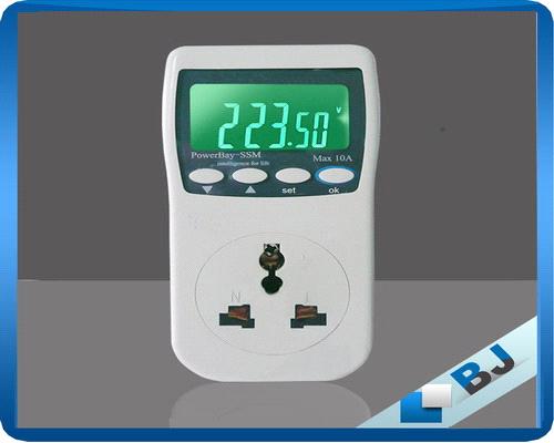
you could maybe get one of these afterwards to final check it.make sure it will do the job as there are different ones with different features
China_portable_plug_in_power_meter20111081656179.JPG
 
if you set with dim bulb tester you will need to reset with it plugged in directly .
turn it down in-between as it will rise the current when plugged in directly .
try first with bulb tester .
4.2mv looks like it will be safe .
you could maybe get one of these afterwards to final check it.make sure it will do the job as there are different ones with different features
China_portable_plug_in_power_meter20111081656179.JPG

I conected the DMM to the chassis (red) and to the earth in the outlet (black). And without turning it on I got 1.286V (AC). And when I turn on the Amp (via a power bar) . I got OL .

Is this OK? I think not. What could be the problem?:scratch2:

Thanks
 
OL is overload .means you need to use a higher setting on the meter .
but it isn't right there is leakage somewhere from the mains to the chassis . i am wondering if you connect them wires to chassis it may cancel it out ? i am not too sure about this though ..
first things first see what the high voltage reads when you set your meter to high AC volts .
or better still unplug the amp . set your meter on ohms and check resistance from the power lead to the chassis .
and also check from secondary side transformer to ground and also to primary ..
i am thinking it has a short in the transformer or one of the wires shorting to ground .
will study the schematic now
 
OL is overload .means you need to use a higher setting on the meter .
but it isn't right there is leakage somewhere from the mains to the chassis . i am wondering if you connect them wires to chassis it may cancel it out ? i am not too sure about this though ..
first things first see what the high voltage reads when you set your meter to high AC volts .
or better still unplug the amp . set your meter on ohms and check resistance from the power lead to the chassis .
and also check from secondary side transformer to ground and also to primary ..
i am thinking it has a short in the transformer or one of the wires shorting to ground .
will study the schematic now

The DMM is auto range but I found a yellow button for changeing the range.
The value is 106V (AC) :thumbsdn:.

I dont understand what you said here :"set your meter on ohms and check resistance from the power lead to the chassis.
and also check from secondary side transformer to ground and also to primary "

Could you axplain me that a little bit. So sorry to bother:D

Thx
 
The DMM is auto range but I found a yellow button for changeing the range.
The value is 106V (AC) :thumbsdn:.

I dont understand what you said here :"set your meter on ohms and check resistance from the power lead to the chassis.
and also check from secondary side transformer to ground and also to primary "

Could you axplain me that a little bit. So sorry to bother:D

Thx

i don't know where this came from [COLOR="black"


ok it looks like its at half the mains supply potential .. first check voltage from the black white / white wires ..keep them connected and measure voltage from earth in your power socket and to amp chassis .
 
i don't know where this came from [COLOR="black"


ok it looks like its at half the mains supply potential .. first check voltage from the black white / white wires ..keep them connected and measure voltage from earth in your power socket and to amp chassis .

119V (AC) . Conecting RED to wires WHITE and BLACK /WHITE; and black to ground on the outlet.
 
just had a thought .. try swapping live neutral ..hot/cold .. at the power plug . this will hopefully make it zero volts on the chassis
 
Back
Top Bottom
