


theodoric
101° Rx = + /_\
My J-Pole project
So I decided not to miss out on the J-Pole bandwagon.
I picked up a copy of Joseph Carr's Practical Antenna Handbook (4th edition) and the American Radio Relay League's ARRL Antenna Book, and found they both recommended the J-Pole as well. Carr's math was a little different than the schematic linked in another thread (that I can't currently locate the link to), so I went with his, as the source is known.
Tuning the length to a wavelength of 98MHz (halfway through the 88-108MHz band), I got the following dimensions:
3/4 wave element: 90.18"
1/4 wave element: 30.12"
coax attachment point: 2.95"
spacing between elements: 2.82"
While it would be optimum to put the thing on top of my two-story roof, the line length of over 100' would result in a huge line loss, and besides, I wasn't in the mood to get up on the roof in December, and I certainly wasn't in the mood to run cable through the attic, down through the walls, under the house, and up into the living room. Seeing as there was a perfectly good wall nearby, with a suitable area conveniently obscured by blinds, and only a dozen feet away, I decided to give it a try.
Components:
1 - 10' length 1/2" copper pipe
1 - 5' length 1/2" copper pipe
2 - 1/2" 90 degree copper elbows
2 - 1/2" pipe caps
2 - 1/2 copper pipe straps
2 - 1/4" copper pipe straps
4 - #10 - 32tpi x 1/2" brass machine screws
4 - #10 - 32tpi brass machine nuts
8 - #10 brass washers
6 - 1/2" Oatey nylon Pipe Support Clamps (part #33916)
12 - #6 x 1" Philips head coarse thread drywall screws
Parts and tax were about $12.
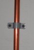
Using a pipe cutter, I cut the pipes to length, fit them with the caps, elbows, and support clamps. The nylon support clamps act as both mounting hardware and insulators, and keep the J-Pole approximately 1/8" from the wall.
I put the 1/4" pipe straps in the vise and flattened them out. The mounting holes matched perfectly with the 1/2" pipe straps. I bolted the copper pipe straps together with the brass bolts, nuts, and washers.
Then I mounted the whole assembly to the wall with the drywall screws, making sure that the spacing between elements remained 2.82" when mounted.
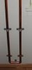
The whole thing came out very clean, and is completely hidden from view (except the top 8") by the window blinds.
Connection from the J-Pole is via 15' Belden RG-6 75 Ohm shielded coax cable.
So I decided not to miss out on the J-Pole bandwagon.
I picked up a copy of Joseph Carr's Practical Antenna Handbook (4th edition) and the American Radio Relay League's ARRL Antenna Book, and found they both recommended the J-Pole as well. Carr's math was a little different than the schematic linked in another thread (that I can't currently locate the link to), so I went with his, as the source is known.
Tuning the length to a wavelength of 98MHz (halfway through the 88-108MHz band), I got the following dimensions:
3/4 wave element: 90.18"
1/4 wave element: 30.12"
coax attachment point: 2.95"
spacing between elements: 2.82"
While it would be optimum to put the thing on top of my two-story roof, the line length of over 100' would result in a huge line loss, and besides, I wasn't in the mood to get up on the roof in December, and I certainly wasn't in the mood to run cable through the attic, down through the walls, under the house, and up into the living room. Seeing as there was a perfectly good wall nearby, with a suitable area conveniently obscured by blinds, and only a dozen feet away, I decided to give it a try.
Components:
1 - 10' length 1/2" copper pipe
1 - 5' length 1/2" copper pipe
2 - 1/2" 90 degree copper elbows
2 - 1/2" pipe caps
2 - 1/2 copper pipe straps
2 - 1/4" copper pipe straps
4 - #10 - 32tpi x 1/2" brass machine screws
4 - #10 - 32tpi brass machine nuts
8 - #10 brass washers
6 - 1/2" Oatey nylon Pipe Support Clamps (part #33916)
12 - #6 x 1" Philips head coarse thread drywall screws
Parts and tax were about $12.
Using a pipe cutter, I cut the pipes to length, fit them with the caps, elbows, and support clamps. The nylon support clamps act as both mounting hardware and insulators, and keep the J-Pole approximately 1/8" from the wall.
I put the 1/4" pipe straps in the vise and flattened them out. The mounting holes matched perfectly with the 1/2" pipe straps. I bolted the copper pipe straps together with the brass bolts, nuts, and washers.
Then I mounted the whole assembly to the wall with the drywall screws, making sure that the spacing between elements remained 2.82" when mounted.
The whole thing came out very clean, and is completely hidden from view (except the top 8") by the window blinds.
Connection from the J-Pole is via 15' Belden RG-6 75 Ohm shielded coax cable.
Attachments
Last edited:


