• The move to the new server is done. There are some software and database maintenance updates in process. This has us passing the hat around to help out. We appreciate any donations. Seriously, even a dollar helps. The payment page may be found here - https://www.audiokarma.org/support.html

SONY TA-1066: recap and restoration

Wombaton

Active Member
Who cares about the sound? I really love the aesthetics of these early SONY amps, Just go here and pick the first ten (sans TA-11, of course) and I love all of them :biggrin:

This is my new restoration project after polishing off one for Kenwood KA-5002. Same as before, I am creating a parts replacement spread sheet in Excel that should be easily convertible into a BOM. Will share it with the community using google drive.
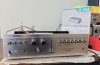
IMG_1165.jpeg

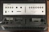
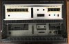
Here are some fresh nude photos:
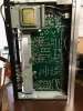
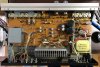
IMG_1153.jpeg IMG_1154.jpeg IMG_1155.jpeg IMG_1156.jpeg IMG_1157.jpeg IMG_1158.jpeg

This cute little thing seems to work, but is very dirty inside, which results in frequent channel cutout when I try to push or wiggle any controls. So, the first order of business is face plate removal and deep cleaning.

Wmbtn
 
Register to hide this ad
Semiconductors in play

Here is the list of what is inside per service manual. There is a considerable number of 'bad actors' here (highlighted in red). I am including possible subs for all positions (just in case; see last column) and would appreciate any critique and/or advice from the community:

Transistors:
Q101,Q201 | Phono amp | 2SC632A | noise/failure | KSC1845F
Q102,Q202 | Phono amp | 2SA705 | | KSA992F
Q103,Q203 | Flat amp | 2SC632A | noise/failure | KSC1845F
Q104,Q204 | Paraphase amp | 2SC632A | noise/failure | KSC1845F
Q105,Q205 | Paraphase amp | 2SC632A | noise/failure | KSC1845F
Q106,Q206 | Predriver | 2SA678 | | KSA1015, KSA1013
Q107,Q207 | DC bias supply | 2SC634A | | KSC945CG, KSD1616A
Q108,Q208 | Driver | 2SC1124 | gain decrease | KSC2690, 2SC4793, KSC4793
Q109,Q209 | Driver | 2SA706 | gain decrease | KSA1220, 2SA1837, KSA1837 --> all obsolete now; use KSA1381ESTU? TTA004B (Toshiba)?
Q110,Q210 | Power amp | 2SC1061 | | KSD526Y, MJE15032
Q111,Q211 | Power amp | 2SA671 | | KSB596, MJE15033

Diodes:
D101,D201 | Output DC bias adjustment | SV-04F --> Unobtanium, but see insightful discussion here.
D301--D304 | Rectifier | 10D-2 (If = 1.5A, Vr = 200V) | SBYV27-200-E3/54
 
Here is the link to my SONY TA-1066 rebuild google drive folder with an Excel sheet for parts replacement:

https://drive.google.com/drive/folders/1TwH1rYY_b1SSNHtBTFI-4f6NOol5zIns?usp=sharing

A few notes:

for the 2SA706....maybe a BD788G or a beefier D45VH10G would work?

I appreciate the info! It looks like 2SA706/2SC1124 drivers will need to be changed as a pair. KSA1220A/KSC2690A is the recommended replacement and I even have some KSC2690 left over, but unfortunately KSA1220A is going the way of the dodo. So, for now I decided to try the Toshiba TTA004B/TTC004B combination (seems to be an acceptable option with KSA1220 becoming extinct) and see how that works out.

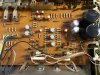
This time I am really trying to match the sizes and lead spacing of the replacement caps to insure tight positioning that is flush with the board. As can be seen from the photos, all the grey colored Elna caps (the larger ones) are flush, while all of the smaller orange ones are floating above. I am hoping to have all the replacements sit flush, which is easy here, as lead spacings for capacitor placement across the board are standardized to 5mm -- with a few rare exceptions.

One of these exceptions are the main filter caps that are mounted 'through the hole' on the board here, rather than being 'snap ins.' Their lead spacing seems to be 12.5mm.

I like to refresh resistors with power ratings above 1/2-1W, but that is highly optional. RT101-201 trimpots used here have pretty goofy footprints. I was not able to match them well, so will have to go with generic Bourns ones and extend their leads as needed.

IMG_1175.jpeg

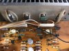
BTW, the two transistors with protruding heat sinks to the left and right of the trimpot are the 2SA706/2SC1124 driver pair.

As usual at this stage, I have a bunch of questions about how to proceed with cleaning, repair and restoration. Will ask these as individual posts within this thread, so that they are easy to quote and address. Will appreciate any comments and advice.

THX,

Wmbtn
 
Last edited:
SONY TA-1066 PCB takes the cake for layout neatness!

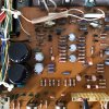
This is some exceptionally nice design: literally everything is mounted on one board with all the elements arranged by type, like military units in an army. The board is easily accessible from top and bottom, which should make replacing parts a breeze.

Power amp:
IMG_1169.jpeg
The little caps in C116-216 positions that look like pomegranate seeds are 2.2 uF tantalums.

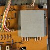
Phono amp that was hidden under its own protective cover in the post #1 photos:
IMG_1168.jpeg

Every part is marked out clearly and, as already mentioned, most lead spacings are 5mm.
 
A couple of quick notes: the orange Elna caps are low leakage. UKLs are a readily available low leakage replacement, or you can use film caps if they will fit. The "cover" on the phono section is a shield. Be sure to put it back in place when you're done.
 
Last edited:
A couple of quick notes: the orange Elna caps are low leakage. UKLs are a readily available low leakage replacement, or you can use film caps if they will fit. The "cover" on the phono section is a shield. Be sure to put it back in place when you're done.

I am mostly following @hopjohn's newbie guide on capacitor replacement. So, all smaller caps, including Elna 'orange jackets,' are being replaced with Wima film (up to 3.3 uF inclusively), which leaves only 33 uF low leakage caps that are being replaced with Nichicon UKL.
 
Face panel disassembly

With some effort, both the face panel and the supporting front part of the chassis were taken off, leaving me with good access to pots and sliders for cleaning:

IMG_1166.jpeg IMG_1167.jpeg IMG_1171.jpeg

Treble / bass knobs were easy to pull off, but I hit a snag with volume and balance level covers, as these were glued on permanently with some superglue or maybe epoxy. Had to apply a 'two spoon' trick to pull them off and will need to think about what could be done to mount them again without glue.

Interestingly, the front panel design has all the decorative button covers attached, which us pretty handy but may make it more difficult to give them a thorough cleaning.

On my unit, practically all screws holding things in place in this area were frozen solid, so an application of penetrating oil followed by using an impact driver were necessary to get them un-stuck.
 
How do I clean and lubricate push-button switches?

So, here is my first question for the community. This model, same as quite a few others, has these rather delicate push-button switches -- lots of them, actually:

IMG_1173.jpeg IMG_1174.jpeg

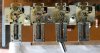
It looks like they still carry some old lubricant (the orange-yellowish stuff) that has partially congealed. Therefore, I am looking for advice on how to clean and re-lubricate them. If at all possible, I would highly prefer NOT to disassemble them beyond the state shown in the photos, as, again, they look rather delicate and fragile, so I am not sure I will be able to put them back together again.
  • So, should I try to lift up as much of the old lubricant as possible with alcohol / cotton swabs?
  • For cleaning (of everything), I have the usual combo of Deoxit contact cleaner D5 / contact protector gold G5. Would that be sufficient here, or should I follow up with a more serious lubricant?
  • Any particular areas on / inside / below these switches I should pay special attention to?
These switches are definitely dirty and problematic at the moment, as I am hearing audio cutting in and out when I am operating them (like, e.g., Stereo/Mono mode switch).

If anyone can share some wisdom about this, I'd be most grateful.

THX,

Wmbtn
 
Handling the power switch

IMG_1172.jpeg

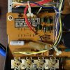
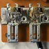
I am also wondering if anyone have dealt with this kind of power switch before. Is it a good idea to try opening it up for internal cleaning and could it be easily reassembled after that? A switch from the Kenwood amp I'd recently handled, came apart easily and cleaned up nicely, but was an enormous pain to put back together again -- to a point where you feel it may be gone for good. Therefore, I am trying to proceed with due caution here.

The orange thing attached to the switch is CP301 'encapsulated component,' which is a 0.033F cap + 120Ω resistor. I wonder if I should just throw it out and do a Littlefuse triac (Q4025L6) + 100Ω / 2 or 3W resistor mod instead? Not sure how much such switches may be prone to arcing in such a low-power amp, but doing a triac mod seems to be a good idea regardless.

Again, any comments are most welcome!

THX,

W.
 
Balance slider disassembly for cleaning

This thing was pulled apart for deep cleaning. Wiggling the balance knob during initial testing resulted in sound cutouts.

IMG_1171.jpeg

Here is what is inside (the parts shown have already been cleaned and re-lubricated with Deoxit gold):

IMG_1177.jpeg IMG_1178.jpeg

It seems that there has been a previous attempt to lubricate this slider that did not go so well -- it was full of some gunk inside.
Note all the delicate contact pads attached to the shifter handle piece in the second photo. Their surfaces were completely covered with patina / oxide film; now cleaned and re-lubricated.
Also, this piece includes a little spring-loaded ball bearing that ensures that the shifter makes a 'click' in the neutral position.

And here is the back of the shifter with wires still attached:

IMG_1179.jpeg

I believe what is actually being used here is the two black contact strips on top. These were also very dirty; now cleaned with isopropyl alcohol and sparingly re-lubricated.

Hopefully this shifter will be working much better after reassembly.
 
Volume slider cleaning

IMG_1203.jpeg

Similar construction as the balance slider -- only bigger. Since there is no need to 'click' this shifter in any specific position, the little spring and ball bearing assembly is missing. Contact tracks inside extra dirty and covered with soot. I used up an untold number of q-tips cleaning this stuff up. Face part of the slider was full of slimy grease, maybe from multiple attempts to lubricate it without complete disassembly?

The reassembled balance slider is also shown in the photo (in the background). For now, I taped it up to avoid any new dust and dirt from getting inside.
 
Last edited:
Cleaning the buttons

IMG_1206.jpeg
Removing old grease from the mechanical parts of the button assemblies (very delicate!) with cotton tips and alcohol. In this photo, the one on the left is clean (sort of), while the one on the right is in its original state. Will re-lubricate the mechanical parts with Super Lube Synthetic Multi-Purpose Grease when done. I had to temporarily remove extra gate shaped supports, as with them in place the rotating part of the switch cannot be moved all the way to clean all the area underneath it.

IMG_1209.jpeg
And in this side view we can see the electrical part of the switch. I am NOT going to disassemble this unless I am completely out of options -- just do regular deoxit treatment for now and see what happens.

 
Last edited:
Binding posts upgrade

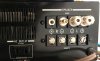
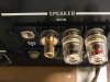
While I was at it, replaced one set of original screw-type terminals with modern binding posts that can handles banana plugs and spades. This is how my work in progress looks:

IMG_1204.jpeg IMG_1205.jpeg

These are inexpensive generic binding posts, but I appreciate that they are so well insulated, since they have to be mounted in such close quarters. As one can see, this installation is not 100% reversible to its original state, since I had to clip little 'ears' off each original terminal to be able to hide the remaining circular pieces under the plastic coatings of the new posts.

The second set of terminals is staying in its original state -- even if simply to illustrate what this state looks like.
 
Nice work Wombaton, a very spoilt little TA-1066 indeed :).

In regards to the power switch, it looks like you still have one unused pair of contacts on the near side of your photo. You could always jumper from each currently used contact across to it's unused counterpart to then use both sets of contacts (increasing current capability). Also a good idea to make sure that the power switch and main fuse are switching the live, so often these were wired incorrectly from the factory in my experience. I guess this is not really applicable to you if you are in an area where the power plug is a 2 pin non polarised plug.
 
Yes, it may become the most pampered amp of this kind when I am done with it!

In regards to the power switch, it looks like you still have one unused pair of contacts on the near side of your photo. You could always jumper from each currently used contact across to it's unused counterpart to then use both sets of contacts (increasing current capability).

And you are absolutely correct! This one has no switchable AC plugs, and therefore one pair of power switch contacts is unused. When adding a TRIAC mod, these contacts usually get bridged as a standard part of this upgrade.

Also a good idea to make sure that the power switch and main fuse are switching the live, so often these were wired incorrectly from the factory in my experience. I guess this is not really applicable to you if you are in an area where the power plug is a 2 pin non polarised plug.

I will need to double check how exactly the main fuse is wired, but its default position in the schematic (for the US model) looks appropriate. The problem is that on the amp it seems to be soldered in, rather than sitting in a holder (black thing in the photo):

IMG_1156_with_fuse.jpg

So, I will need to modify this whole assembly, installing a modern fuse holder -- and will need to find a good place to mount it that is not too far away from its original location.

Also, in principle, it should be possible to change the power cord to polarized plug or even polarized plug with grounding (by attaching the grounding wire to the chassis, I presume). But such cords are thicker than the original and will require some surgery to the back plate, like expanding the power cable hole quite a bit to accept a new cable gland large enough to accommodate a thicker cord. So, you need to completely remove the back plate and then use good metal cutting tools and a drill press, which sounds like too much fuss.
 
Yes, it may become the most pampered amp of this kind when I am done with it!

Sounds like she will be a keeper :thumbsup:. I have a TA-1066 here that l will probably restore down the track.

And you are absolutely correct! This one has no switchable AC plugs, and therefore one pair of power switch contacts is unused. When adding a TRIAC mod, these contacts usually get bridged as a standard part of this upgrade.

Fair enough, sorry l forgot you were thinking of doing the triac mod.


I will need to double check how exactly the main fuse is wired, but its default position in the schematic (for the US model) looks appropriate. The problem is that on the amp it seems to be soldered in, rather than sitting in a holder (black thing in the photo):


So, I will need to modify this whole assembly, installing a modern fuse holder -- and will need to find a good place to mount it that is not too far away from its original location.

Also, in principle, it should be possible to change the power cord to polarized plug or even polarized plug with grounding (by attaching the grounding wire to the chassis, I presume). But such cords are thicker than the original and will require some surgery to the back plate, like expanding the power cable hole quite a bit to accept a new cable gland large enough to accommodate a thicker cord. So, you need to completely remove the back plate and then use good metal cutting tools and a drill press, which sounds like too much fuss.

You shouldn't have to alter the fuse holder, if they are wired incorrectly (our Sony's here had 3 pin polarised plugs from factory, but my TA-1066 was still incorrect) l just rewire the transformer primary wiring so as the live goes to main fuse/power switch and then onto transformer. Neutral should just go straight to transformer if it is a model (like the TA-1066) where the power switch only switches one side.

IF you did want to go with a 3 pin earthed AC lead, you should be able to use a small round file to file out the factory plastic strain relief bushing once removed from rear panel. You can make it just the right size to firmly but not over grip a standard round 3 wire lead, l have done it many times. You won't have to remove or modify the rear panel.[/QUOTE]
 
Last edited:
And the fun continues. After thorough cleaning and re-lubrication of both electrical and mechanical parts of all the knobs, sliders and buttons this little thing is working. I have not checked all possible input / output combinations, but the sound I am getting now is pretty balanced, with zero distortion, cutouts or static when moving controls.

At that point I went ahead and recapped everything, which was fast, as there are not too many capacitors here to take care of. Currently, I got everything done on my list except for the 3300 uF mains (still on order) and some lower capacitance mylars I may decide to refresh. The amp still works with no issues. Here are some photos:

IMG_1221.jpeg
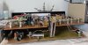
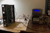
Testing the sound on isolation transformer; volume / balance sliders and phones / aux jacks taped up to prevent any dust from getting in.

IMG_1222.jpeg
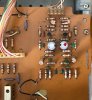
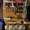
Top view of the main PCB; it is easy to see the new caps, especially the red colored Wima films.

Spending a bit of preparation time to measure out capacitor sizes paid off. All the replacement capacitors easily mounted flush with the board, which looks clean and professional, as I would hope.

Next step -- transistor replacement and that is going to be a bit of a mess. I will do a separate post to cover details.
 
Last edited:
Back
Top Bottom