

You are using an out of date browser. It may not display this or other websites correctly.
You should upgrade or use an alternative browser.
You should upgrade or use an alternative browser.
SONY TA-1066: recap and restoration
- Thread starter Wombaton
- Start date

Wombaton
Active Member
As it turns out, there is some life left in this thread. About the last thing left to do with this amp was refreshing thermal contacts between the output transistors and heat sink -- potentially combined with replacing these transistors, since the pairs I got on Left and Right were different:
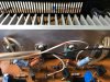
After looking at a number of pro and contra opinions in regards to doing the replacement, I decided to do it anyway -- partially as an exercise -- using KSD526Y / KSB596YTU 4 Amp components.
Up until this moment, this restomod has been a smooth sailing (except for the controls cleaning part), primarily due to this amp being so simple and well laid out. But the flood gates of hell opened the moment I started loosening the screws that connected the old outputs to the sink. However, in retrospect, I am still glad that I decided to go ahead and change the outputs, as that experience surely taught me a lot.
After looking at a number of pro and contra opinions in regards to doing the replacement, I decided to do it anyway -- partially as an exercise -- using KSD526Y / KSB596YTU 4 Amp components.
Up until this moment, this restomod has been a smooth sailing (except for the controls cleaning part), primarily due to this amp being so simple and well laid out. But the flood gates of hell opened the moment I started loosening the screws that connected the old outputs to the sink. However, in retrospect, I am still glad that I decided to go ahead and change the outputs, as that experience surely taught me a lot.
Wombaton
Active Member
Heat sink screws cooked?
At least, that is my working hypothesis. I lost three out of four connecting screws when extracting or later re-fitting them to the heat sink holes. Some screw heads got destroyed and one screw broke apart inside a hole. I suspect that the hole grooves had been partially stripped (and unfortunately I do not have tools to remove the broken screw stump from the hole). Notably, the greatest damage I found was on the side of the transistor pair that is not original, i.e., these screws and grooves were probably stripped during that old repair.
Now, the contact between the outputs and the sink was practically non-existent. Old thermal grease had turned to powder, plus mica sheets used here were super thick. Hence the thought highlighted above: if the amp had been used in such condition for an extended period of time, most of the thermal contact between the transistors and the heat sink would have been concentrated around the retaining screws and their holes, which would cause the screws to become more brittle than usual.
Speaking of these screws, they are not some run of the mill stuff: SONY used a 'B 2.6 x 8' here (i.e., 2.6 mm diameter by 8 mm length), which is not something I had in stock. Such screws are available on eBay, but only for a handful of US suppliers. Here is what I got as a replacement:
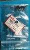
Original, Japanese made screws that are used, apparently, in miniature drones and robots (and cost accordingly). Silver screws in the photo are old ones, while new ones are darker in color.
At least, that is my working hypothesis. I lost three out of four connecting screws when extracting or later re-fitting them to the heat sink holes. Some screw heads got destroyed and one screw broke apart inside a hole. I suspect that the hole grooves had been partially stripped (and unfortunately I do not have tools to remove the broken screw stump from the hole). Notably, the greatest damage I found was on the side of the transistor pair that is not original, i.e., these screws and grooves were probably stripped during that old repair.
Now, the contact between the outputs and the sink was practically non-existent. Old thermal grease had turned to powder, plus mica sheets used here were super thick. Hence the thought highlighted above: if the amp had been used in such condition for an extended period of time, most of the thermal contact between the transistors and the heat sink would have been concentrated around the retaining screws and their holes, which would cause the screws to become more brittle than usual.
Speaking of these screws, they are not some run of the mill stuff: SONY used a 'B 2.6 x 8' here (i.e., 2.6 mm diameter by 8 mm length), which is not something I had in stock. Such screws are available on eBay, but only for a handful of US suppliers. Here is what I got as a replacement:
Original, Japanese made screws that are used, apparently, in miniature drones and robots (and cost accordingly). Silver screws in the photo are old ones, while new ones are darker in color.
Wombaton
Active Member
Out with the old outputs, in with the new, but not so fast
Here is a view of the heat sink with no transistors attached:

Unfortunately, losing one of the holes meant that I would not be able to mount the new transistors the same way the old ones were positioned. On the other hand, this sink has extra pre-drilled holes, so I could still attach all four transistors without the hassle of making brand new mounting holes.
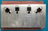
In the end, I went for a symmetric configuration where the new transistors were attached 'heads up,' compared to the original assembly, with silpads for thermal interfaces. Here is an image of a dry-run fit with new (darker color) screws. The clogged mounting hole is shown by a red circle:
A compounding problem which required this positioning was that, when removing the old transistors from the PCB, I lost some traces on the foil side -- these appear to be very fragile and lift easily. In retrospect, I recommend cutting old transistor leads first and then removing the remaining ends, while using a desoldering braid around them instead of a solder sucker. The photo below shows the original state of the output transistor attachment locations on the PCB foil side. Note how closely spaced the attachment points for individual leads are. In the end, I lost two of these locations because of lifting foil traces.

Here is a view of the heat sink with no transistors attached:
Unfortunately, losing one of the holes meant that I would not be able to mount the new transistors the same way the old ones were positioned. On the other hand, this sink has extra pre-drilled holes, so I could still attach all four transistors without the hassle of making brand new mounting holes.
In the end, I went for a symmetric configuration where the new transistors were attached 'heads up,' compared to the original assembly, with silpads for thermal interfaces. Here is an image of a dry-run fit with new (darker color) screws. The clogged mounting hole is shown by a red circle:
A compounding problem which required this positioning was that, when removing the old transistors from the PCB, I lost some traces on the foil side -- these appear to be very fragile and lift easily. In retrospect, I recommend cutting old transistor leads first and then removing the remaining ends, while using a desoldering braid around them instead of a solder sucker. The photo below shows the original state of the output transistor attachment locations on the PCB foil side. Note how closely spaced the attachment points for individual leads are. In the end, I lost two of these locations because of lifting foil traces.
Wombaton
Active Member
In with the new, finally
Some images with the new transistors attached to the sink and fitted with longer connecting leads -- covered with shrink wrap on the transistor end and to be soldered to the PCB directly on the other end:
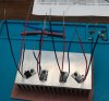
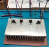
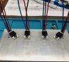
I used the original PCB openings for output transistor leads to pull the new wires through (22 AWG). The openings had to be opened up a bit to make that happen. The only new hole I had to drill was for Q210 emitter, filling the original hole with a conducting stub (a look at the PCB foil side diagram should explain why). Two images below show how the finalized assembly looks from top and bottom:
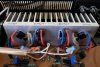
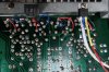
The extra thing on the right side of the second image is the triac with its wiring, this time permanently mounted to the chassis bottom with some thermal grease for better contact.
After this repair was finished, I readjusted the DC bias, turned the amp on and everything worked with no issues. By far, not the neatest or highly reversible repair, but it came out Ok in the end.
Some images with the new transistors attached to the sink and fitted with longer connecting leads -- covered with shrink wrap on the transistor end and to be soldered to the PCB directly on the other end:
I used the original PCB openings for output transistor leads to pull the new wires through (22 AWG). The openings had to be opened up a bit to make that happen. The only new hole I had to drill was for Q210 emitter, filling the original hole with a conducting stub (a look at the PCB foil side diagram should explain why). Two images below show how the finalized assembly looks from top and bottom:
The extra thing on the right side of the second image is the triac with its wiring, this time permanently mounted to the chassis bottom with some thermal grease for better contact.
After this repair was finished, I readjusted the DC bias, turned the amp on and everything worked with no issues. By far, not the neatest or highly reversible repair, but it came out Ok in the end.
Wombaton
Active Member
Conclusions
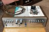
I am listening to the rebuilt subject of this thread as I am writing this message. Sonically, it seems to be a very average amp, but that is according to the 70s hi-fi standard. For non critical applications that do not require more power it should still be totally fine. It also has a rather nice vintage look, although, being an entry level model, all of its knobs and buttons are plastic (but seems to be good quality plastic nonetheless). Incidentally, the volume and balance knob covers on my amp were glued in place with epoxy. I was barely able to remove them without breaking, but during the final assembly they clicked back in perfectly and are holding on tightly without any glue.
As far as rebuilding goes, this amp is very simple to work on and I recommend it as a good starter project -- especially so if one does NOT have to change the output transistors. I believe, such entry level SONYs can still be had for not much money (mine was around $40 or 50) and new parts investments are equally modest (maybe less than $60 for absolutely everything in my case, including many leftovers and spares).
One thing I am not sure of is how good this amp could be for spinning vinyl. My impression is that its phono preamp is a bit noisy. I have not done anything to modify it.
The amp is running a tiny bit warm, even when idling, with DC bias adjusted to 25 mV. By now, I have racked up many hours of listening, including long continuous sessions, and the temperature never seems to go up. Hopefully the new silpads and output connector screws will hold.
And to wrap things up, here is the money shot with all the parts that were taken out:
I am listening to the rebuilt subject of this thread as I am writing this message. Sonically, it seems to be a very average amp, but that is according to the 70s hi-fi standard. For non critical applications that do not require more power it should still be totally fine. It also has a rather nice vintage look, although, being an entry level model, all of its knobs and buttons are plastic (but seems to be good quality plastic nonetheless). Incidentally, the volume and balance knob covers on my amp were glued in place with epoxy. I was barely able to remove them without breaking, but during the final assembly they clicked back in perfectly and are holding on tightly without any glue.
As far as rebuilding goes, this amp is very simple to work on and I recommend it as a good starter project -- especially so if one does NOT have to change the output transistors. I believe, such entry level SONYs can still be had for not much money (mine was around $40 or 50) and new parts investments are equally modest (maybe less than $60 for absolutely everything in my case, including many leftovers and spares).
One thing I am not sure of is how good this amp could be for spinning vinyl. My impression is that its phono preamp is a bit noisy. I have not done anything to modify it.
The amp is running a tiny bit warm, even when idling, with DC bias adjusted to 25 mV. By now, I have racked up many hours of listening, including long continuous sessions, and the temperature never seems to go up. Hopefully the new silpads and output connector screws will hold.
And to wrap things up, here is the money shot with all the parts that were taken out:


Wombaton
Active Member
Well, it is an entry level model, so it is not going to rock your socks off. A beefier model, like a SONY TA-11XX will sound better. But for low-level listening in a smaller room it works fine and to my ears it sounds pretty neutral. Bass response was improved after the recap but it remains restrained. My Sansui AU-505 is a bit warmer and more dynamic in comparison.