• The move to the new server is done. There are some software and database maintenance updates in process. This has us passing the hat around to help out. We appreciate any donations. Seriously, even a dollar helps. The payment page may be found here - https://www.audiokarma.org/support.html

SONY TA-1066: recap and restoration

Dear All,

Thank you very much for your comments and advice! I have been trying to solicit opinions on what to do with the output transistor pairs in a separate thread; still deciding what to do about them and working on refreshing some resistors / trimpots in the meantime.
Will push another update once I have more interesting images to share.

Cheers,

W.
 
If it's working and sounding right, I would just leave it. Do you have a transistor tester or one built into a multi meter that can test for HFE? If they are close it isn't a problem. I do like to replace some older trim pots though. Like the type Marantz liked to use in the 70's. Even cleaning the carbon off of them they still will tend to drift. If you can get the multi turn Bourn trimmers to fit they are nice since it's easier to dial them in.
 
I normally go to Little Diode for those hard to find old stock parts that are just a better fit than something modern. It can be hit and miss though. The last items I bought from them were some arcane old regulators. I didn't want to modify the PCB and connections for something modern in a different package. The prices are higher. Probably due to tariffs. I know anything I get from England costs a lot more.

Well being born in England, I should've remembered the contradictory language of Value Added Tax. There is no value in added taxation! But every country has its faults. I rarely find myself coming across a site that Norton flags as unsafe. I just trusted the address when I clicked on go anyway. And yes, everything is more expensive in the UK. But it shouldn't be that expensive! Considering I found the transistors New Old Stock, never used for 89yen a piece!
 
Dear All,

Thank you very much for your comments and advice! I have been trying to solicit opinions on what to do with the output transistor pairs in a separate thread; still deciding what to do about them and working on refreshing some resistors / trimpots in the meantime.
Will push another update once I have more interesting images to share.

Cheers,

W.
I found an interesting company that instead of using PNP and NPN transistors which they found impossible to match to any degree of satisfaction, They used NPN only and simply made a module that flips it's operation. The amplifier is one of those ultra expensive units so it's not really relevant but I feel your pain. Finding matched pairs of transistors, and multiple sets that match is pretty much an impossibility.
 
Well being born in England, I should've remembered the contradictory language of Value Added Tax. There is no value in added taxation! But every country has its faults. I rarely find myself coming across a site that Norton flags as unsafe. I just trusted the address when I clicked on go anyway. And yes, everything is more expensive in the UK. But it shouldn't be that expensive! Considering I found the transistors New Old Stock, never used for 89yen a piece!
I agree. I only use them if I can't find the NOS part I need anywhere else.
 
Trimpots and output emitter resistors

If it's working and sounding right, I would just leave it. Do you have a transistor tester or one built into a multi meter that can test for HFE? If they are close it isn't a problem. I do like to replace some older trim pots though. Like the type Marantz liked to use in the 70's. Even cleaning the carbon off of them they still will tend to drift. If you can get the multi turn Bourn trimmers to fit they are nice since it's easier to dial them in.

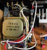
So, that was the next round of updates, as shown here:

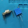
IMG_1240a.jpeg IMG_1241.jpeg

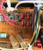
The original trimpots are horrible and have a huge footprint that I was not able to match with a modern replacement. Indeed, I got Bourns multiturn trimmers as replacements, but had to extend the middle lead wire to make them fit the PCB openings. Here is the result:

IMG_1242.jpeg

As can be seen from this image, I also refreshed the output emitter resistors -- R138/R238, dual 0.47 Ohm, 2W -- with whatever I had in my spares box, which was a combination of Vishay and Panasonic 0.47 Ohm 5% 3W. After taking this photo, I covered the exposed extended middle leads of the new trimmers with pieces of electrical tape.

Since the resistance values of the original trimpots have drifted so much (one of them was especially bad), I had to do the DC bias adjustment -- even if a crude one for the time being -- with the new trimmers. It took a bit of time and multiple iterations, but I managed to get the bias in both channels to 25 mV (per service manual) +- ~0.2 mV. And so it works. Powered the amp up on DBT and then gradually on my isolation transformer / variac, played some music -- no issues.

In the upcoming episode: the newly arrived main filter caps replacement and the remaining 1/2W C-composition resistors also come out.
 
Nice. Those old open frame trimmers are the worst. The multi turn are the best choice. I have used the Bourn single turn trimmers before though.
 
Nice. Those old open frame trimmers are the worst. The multi turn are the best choice. I have used the Bourn single turn trimmers before though.

I have also used single-turn trimmers before -- on my Kenwood KA-5002 rebuild:

IMG_1149.jpeg

They work fine, but is feels like multi-turn ones are easier to adjust precisely, especially if dealing with a 22K Ohm resistor in the case of of this SONY amp.
 
Filter caps and resistors

3300 uF filter caps C308/309 were replaced with 4700 uF caps, Nichicon UVR1J472MRD6:

IMG_1244.jpeg

These replacements fitted the PCB openings very well, ensuring a snug placement on the board. The new caps measured out on the lower side of the nominal, actually closer to 4400 uF. Could be, though, that my (battery operated) testers are having problems with higher-capacitance items.

In general, I am impressed that this puny amp (rated as 2x ~18W into 8 Ohm) has a 2x 3300 uF setup to start with. My Kenwood KA-5002 (rated at 30W) had only 2x 2200 uF -- now also upgraded to 2x 4700 uF -- while my KA-4002 and Sansui AU-505 both use only one filtering cap. Here, I went with a more modest upgrade of the filtering caps, as bumping them up by 100+% raises the strain on everything around them, including the diode bridge, wiring, etc.

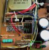
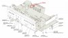
I also replaced all the high-power resistors, bumping up their power ratings:

layout.jpg

The picture shows what went where, including what still remains to be done -- the diode bridge update and a more civilized solution for the main fuse.

Powered the amp on DBT / variac, played some music -- no issues. As expected, it developed an extended LF 'punch' with the new filter caps, or at least that is what I perceived through the test speaker system.
 
Last edited:
Nice. It looks like the board was also used for another model, or models. I see slots for three fuse holders. But it looks like there is metal right under the board, so adding a std. PCB mount fuse holder might not work. Maybe a twist apart fuse holder for the mini glass fuses?
 
Nice. It looks like the board was also used for another model, or models. I see slots for three fuse holders. But it looks like there is metal right under the board, so adding a std. PCB mount fuse holder might not work. Maybe a twist apart fuse holder for the mini glass fuses?

So glad that you asked! The extra fuse slots on the PCB are for the UK and AEP models. And yes, indeed, this is a poor spot to drill into the board to try mounting a more modern fuse holder. The original fuse here is simply soldered in. After some looking around, I managed to find a different place to mount a holder -- without the need to drill into anything:

fuse_location.jpg

Replacing one of the original screws that hold the heat sink assembly with a longer one and using a few spacers here and there allowed me to do the following:

IMG_1250.jpeg

I.e., the original fuse was cut away and a new one was mounted in a modern holder with some extension wires (16 or 18 gauge should be fine). Maybe not the most graceful solution, but it worked with no issues.

In the meantime, I also rebuilt the diode bridge with new diodes and capacitors (per my original Excel restomod sheet). D301-304 10D-2 diodes were replaced with SBYV27-200-E3/54from Vishay:

IMG_1249.jpeg

Everything works with no trouble and at this point there is not much left to do -- unless I decide to replace the outputs.
 
Good job. Much better than soldered in fuses. A Sony power amp I have had soldered in fuses. Someone at some point used fuse holders that clipped onto the burned out fuse caps. The blown fuses were left soldered in place with that fuse holder just clipped onto the old fuses with new fuses clipped into the other side of the holder. Thats the first time I ever saw fuse holders like that.
 
Triac mod for the power switch

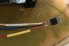
One of the leftovers. As usual, I did a simplified mod with a triac (Littlefuse Q4025L6, 400 V / 25 Amp) and a 100 Ohm / 3 W resistor on the gate lead. Left/right power switch contacts were bridged in the process and the old safety cap was discarded. Here is the general view of the mod before putting shrink wrap in place:

IMG_1251.jpeg IMG_1252.jpeg IMG_1253.jpeg

Thick brown wire attached to the switch is the original 'hot' wire. New thin black wire goes from the switch to MT2. Thick white wire is the original 'load' wire and goes to MT1. New thin red wire with the 100 Ohm resistor goes from the switch (the other set of contacts) to the gate.

Here is the whole thing installed, with the shrink wrap in place. For now, the triac is attached to the heat sink screw. Once I am done refreshing the outputs, I will probably install it in the same place more permanently with some thermal grease at the interface:

IMG_1254.jpeg

Everything works with no issues.
 
I would be concerned about that light gauge lead carrying mains current. If you follow the diagram in the first post of this thread, your line (original brown wire) should connect to MT1, the load (original white wire) to MT2 and the switch should be wired in a circuit from MT2 to gate that includes the resistor. This last wire can be light gauge because it only carries miliamps. The others should be at least the original gauge.
 
I would be concerned about that light gauge lead carrying mains current. If you follow the diagram in the first post of this thread, your line (original brown wire) should connect to MT1, the load (original white wire) to MT2 and the switch should be wired in a circuit from MT2 to gate that includes the resistor. This last wire can be light gauge because it only carries miliamps. The others should be at least the original gauge.

Actually, I forgot to mention this! The gauge of the original and new wires is the same (22 AWG, which seems to be quite sufficient for this low-power amp), but the old ones look much bulkier because of the extra thick layer of plastic insulation around them.

Re which wire goes to which MTX, I am following a later post and schematic (#34 by @EchoWars) in the same thread you quoted. Anyway, as stated in that post, this seems to be a symmetric device, so it may make no difference which wire goes where.
 
Last edited:
Any time they can be installed and have easy access to adjust them its the way to go. I have used the single turn when the multi turn didn't fit the space right to adjust. I have a few tube amplifiers I would like to use the multi turn pots in, but having to try and adjust them horizontally just isn't optimal.
 
Some more cleaning and veneer repair

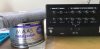
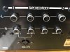
I still had to clean and polish the RCA jacks in the back and decided to try Maas metal polisher. This is expensive stuff, but I saw some AK-ers swearing by it, and it also smells nice! The RCA jacks were quite tarnished, so rubbing them with isopropyl alcohol was doing nothing. Maas is being advertised as wipe on / wipe off, so no rubbing is needed in principle -- unless you want to buff on a very shiny finish. Here are my before / after images:
IMG_1255.jpeg IMG_1256.jpeg

I can't say that these photographs are very successful at showing the difference, but after two consecutive applications the RCA jacks became acquired a mirror like finish with zero tarnish remaining. I am pretty happy with how this stuff worked, plus no strong ammonia smells to deal with.

Now, vinyl veneer cover for this amp looks nice for the most part, except one defect that is unfortunately highly visible:
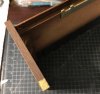
IMG_1257.jpeg

I decided to do a simple fix for this missing piece of veneer by auto-transplant. For some reason, the cover has areas that got veneer but are not at all visible when the amp is fully assembled. Here is one such area highlighted, which is right next to the defect:
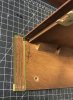
IMG_1258.jpeg

I managed to lift a strip of veneer from that area, shape it and glue it onto the board missing its original veneer piece. I used some version of PVA / white glue to get the job done, which required no weight or clamping. Here is how the transplant looks right after being glued in place. The area from which the strip was cut in also quite prominent in this image:
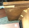
IMG_1259.jpeg

The color match is not perfect and the strip borders are visible. I applied a bit of colored wood filler to blend things in a bit. Here is the final look:
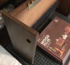
IMG_1260.jpeg IMG_1261.jpeg

Still not perfect, especially if you know where to look, but infinitely better than the original state when the board was completely uncovered. I think, it is not too bad for a 30 min repair.

 
Hi. I recently got a nice TA1066. The previous owner told me that the left channel becomes distorted after a few minutes. The right channel is working fine. I am trying to fix the issue, checked the DC bias. The right channel has a reading of around 23mv but the left channel has a reading only around 3-5mv. I also checked the voltages at Q106 and Q107 (left channel),1.27v and - 1.27v respectively. However, the voltages at these transistors do not stay at 1.27v, it varies when the volume is turned up. Please let me know on what other things that I need to check and other parts that I need to replace. Thanks in advance.
 
Hi. I recently got a nice TA1066. The previous owner told me that the left channel becomes distorted after a few minutes. The right channel is working fine. I am trying to fix the issue, checked the DC bias. The right channel has a reading of around 23mv but the left channel has a reading only around 3-5mv. I also checked the voltages at Q106 and Q107 (left channel),1.27v and - 1.27v respectively. However, the voltages at these transistors do not stay at 1.27v, it varies when the volume is turned up. Please let me know on what other things that I need to check and other parts that I need to replace. Thanks in advance.
Welcome to AK!
You might want to start a new thread with the model you're working on and the issue you're experiencing included in the title. You're likely to get a better response that way.
 
Hi. I recently got a nice TA1066. The previous owner told me that the left channel becomes distorted after a few minutes. The right channel is working fine. I am trying to fix the issue, checked the DC bias. The right channel has a reading of around 23mv but the left channel has a reading only around 3-5mv. I also checked the voltages at Q106 and Q107 (left channel),1.27v and - 1.27v respectively. However, the voltages at these transistors do not stay at 1.27v, it varies when the volume is turned up. Please let me know on what other things that I need to check and other parts that I need to replace. Thanks in advance.

Boryan,

While opening a separate thread is a good idea, I will try to help in place. PLZ keep in mind that I am not a pro in this stuff. But the first thought that comes to my mind is trying to readjust the DC bias. 23 mV on the Right is close to spec, but 3-5 mV on the Left is way too low.

I suggest that you check out post #46 right here in this thread. Original variable resistors that control the bias tend to go bad and on my amp one of them measured out way worse than the other. So, I'd try to replace these resistors with new ones (the type I used is Bourns 3296Y-1-223LF but other types may also work), reset the bias to spec and check if distortion goes away (we could hope but there is no guarantee).

Note that the process of setting the bias takes a bit of time as it keeps drifting, so make sure that your amp is warmed up before you begin measuring. A good approach is to work on both channels simultaneously if you can hook up two voltmeters. Of course, you should use a non-conductive tool to work the resistor or cover your screwdriver with electrical tape.

HTH,

Wmbtn
 
Back
Top Bottom