• The move to the new server is done. There are some software and database maintenance updates in process. This has us passing the hat around to help out. We appreciate any donations. Seriously, even a dollar helps. The payment page may be found here - https://www.audiokarma.org/support.html

MBuras

Restoration is an Addiction
So normally I work on Marantz, Pioneer & Sansui gear but this little integrated has good looks and came at a good price so what the heck. There's not a lot of information out there on this amp so I thought I would contribute what I can by documenting the boards as I work through it.

First things first, I used a DBT to make sure there were no obvious shorts as the playing condition was unknown. That went fine so on went the test speakers with an AUX source. And it plays! Really nicely in fact. No pops, crackles or other signs of bad transistors. Controls are all working well and both channels are even. Testing went so well I put it on my main rig for a listening session. It sounds every bit as good as a Marantz 2230/1060 or even the Pioneer x2x series from the same era. Nice warm sound. The lows were a little muddy and the highs a little crunchy which I attributed to age of components. The soundstage is very nice! Now it's on to a recap and see if we can't bring back some of the original sound.

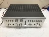
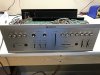
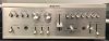
Here's a few pics of the outside. A real gem if you ask me. Great looks and free of any major defects.
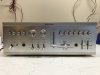
Photo Mar 09, 3 45 31 PM.jpg

Photo Mar 09, 3 45 36 PM.jpg

Photo Mar 09, 3 46 04 PM.jpg

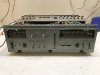
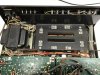
4 screws hold the top cover on. Here's a peek inside.
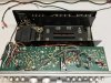
Photo Mar 09, 3 48 19 PM.jpg

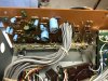
Sony came up with an interesting way to pack a lot into a small space with the phono/pre/power floating on the upper boards and the main amp/heatsink down below. Although that also resulted in a lot of point to point wiring for all the sources. Yikes!

For those without smell-o-vision let me explain the disgusting level of dirt & smell inside this chassis. It seems like a chain smoking squirrel lived inside this case for about 30 years and then curled up in the corner and died. Fuzz, dust, nicotine, sticky residue is pretty much everywhere. I'm thinking about pulling everything out and giving the chassis a full wash down. We'll see.

It has all the original output transistors which is great, although the to-220 case transistors are easily replaced with modern components.

Removing the faceplate is a pretty straight forward operation. Pull the few lever knobs, the volume slider knob and the 2-piece tone control knobs (which are machined metal!). Then there are 3 screws on the bottom front and 3 screws on the inside top of the face. It pretty much falls off after that.
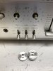
Photo Mar 09, 3 50 08 PM.jpg

Photo Mar 09, 3 52 13 PM.jpg

Photo Mar 09, 3 54 38 PM.jpg

Pretty simple. Then just remove a whole bunch of screws holding all the controls in place and remember where they all go. Actually, just the headphone and aux2 jacks have different screws. The rest are all the same.

That's it for the moment. I'm still working my way through documenting the boards and will post more later.

-Mike
 
Last edited:
Register to hide this ad
Nice well built series. I have the 3200F power amp. Crazy over built and sounds great. It was fun to restore. nice find there! The early 70's Sony stuff is very well made and thought out.
 
One more to better show the level of dirt in this unit. The clean little square was where a bracket was mounted and shows the original anodized surface.
Photo Mar 09, 4 37 02 PM.jpg

Up next are details on the boards.
 
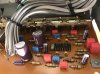
First up is the main amp board. It's mounted to the output heatsink on the bottom level of the amp. There are about 8 wires attached to this board, thoughtfully with friction fit connections, and then 4 screws on the heatsink and the whole assembly comes out.

Photo Mar 09, 3 48 27 PM.jpg

Photo Mar 09, 3 48 27 PM.jpg

Photo Mar 09, 4 19 29 PM.jpg

To remove the main amp board from the heatsink you have to pull the tab screws for all the output transistors. There are also 2 additional screws on that section of the heatsink. And then the output transistors need to be pulled out of their friction fit with the board below. Then the amp board pretty much falls away. Very simple.

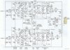
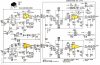
Once I started trying to document the amp board vs. the service manual and schematic parts list I ran into a problem. My board has extra parts not listed on the documents I have. Hmmm....turns out after a little research that Sony made running changes on this amp over its production run and created a revision some refer to as the TA-1150D or just TA-1150 Revised. That made sense as this one has a high serial number. But nowhere online was I able to find a revised service manual or schematic. That is until I used Google Translate to check out a Japanese website. The page appeared to be a very technical analysis of the amp and/or the revisions but the real bonus was a schematic image of sufficient quality to use as a reference source. Sure enough it's exactly what I needed.

Sony TA-1150 Modified Amp Board Schematic.jpg

So here is a verified list of most components on TA-1150 amp board with serial number 806823.

C301/C401 - 0.47uf/50v electrolytic capacitor
C302/C402 - 10uf/10v electrolytic capacitor
C303/C403 - 3pf/50v ceramic capacitor
C304/C404 - 47pf/50v ceramic capacitor
C305/C405 - 220uf/10v electrolytic capacitor
C306/C406 - 4.7uf/25v electrolytic capacitor
C307/C407 - 100uf/50v electrolytic capacitor
C308/C408 - 47uf/50v electrolytic capacitor
C309/C409 - 0.033uf/50v mylar capacitor
C310/C410 - 0.01uf/50v mylar capacitor
C311/C411 - 27pf/50v ceramic capacitor
C551 - 47uf/50v electrolytic capacitor
C552 - 220uf/50v electrolytic capacitor
C560 - 220uf/6.3v electrolytic capacitor

Q301/Q401 - 2SC1362 transistor
Q302/Q402 - 2SC1362 transistor
Q303/Q403 - 2SA678 transistor
Q304/Q404 - 2SC945 transistor
Q305/Q405 - 2SC1124 transistor
Q306/Q406 - 2SA706 transistor
Q311/Q411 - 2SA678 transistor
Q551 - 2SA678 transistor
Q552 - 2SC945 transistor
Q553 - 2AS678 transistor

R308/R408 - 1.2K 1/4 watt resistor **
R310/R410 - 270 1/4 watt resistor **
R312/R412 - 100 1/4 watt resistor **
R316-R319/R416-R419 - 0.47 2 watt emitter resistor (upright)
R322-R323/R422-R423 - 470 1/2 watt resistor
R324/R424 - 10 1/2 watt resistor
R325/R425 - 4.7 1/4 watt resistor **
RV301/RV401 - 1K trimmer

** = these resistors may or may not be covered in some of the glue from nearby capacitors. I am replacing due to some corrosion of leads from glue.

D301/D401 - SH-1S diode
D555/D556 - 1N4148 diode
D557/D558 - 10E4 diode
D559/D560 - 1N4148 diode

Output Transistors:
Q307/Q407/Q309/Q409 - 2SC1060 transistor
Q308/Q408/Q310/Q410 - 2SA670 transistor

And if anyone knows of a more modern solution for those goofy spring metal overload protectors on this board I'm all ears. Seems like they would react way too slow to any potential short, possibly risking damage to the speakers.
 
I bought a TA-1150 brand new circa 1973 to go with my first pair of The Advent Loudspeaker. FWIW, according to a bulletin provided to their dealers and was shown to me, that particular amp was one the Advent Corporation recommended for use with their speakers.
 
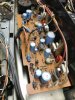
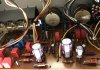
The Tone Amp/Power Supply is up next. This is the only place where it appears a repair had occurred. The original 5B-2 diode at position D551 was gone and has been replaced with 4 individual, modern rectifiers on the backside of the board. Everything else seems original.

Photo Mar 09, 4 18 00 PM.jpg

C151/C251 - 3.3uf/25v electrolytic capacitor
C152/C252 - 3.3uf/25v electrolytic capacitor
C153/C253 - 0.0022uf/50v mylar capacitor
C154/C254 - 0.039uf/50v mylar capacitor
C155/C255 - 0.039uf/50v mylar capacitor
C156/C256 - 0.0022uf/50v mylar capacitor
C157/C257 - 0.039uf/50v mylar capacitor
C158/C258 - 3.3uf/25v electrolytic capacitor
C159/C259 - 47uf/10v electrolytic capacitor
C160/C260 - 220pf/50v ceramic capacitor
C161/C261 - 220pf/50v ceramic capacitor
C162/C262 - 220pf/50v ceramic capacitor
C163/C263 - left open or wire bridge
C164/C264 - 3.3uf/25v electrolytic capacitor
C165/C265 - 0.012uf/50v mylar capacitor
C166/C266 - 0.1uf/50v mylar capacitor
C167/C267 - 0.1uf/50v mylar capacitor
C533 - 220uf/25v electrolytic capacitor
C534 - 33uf/10v electrolytic capacitor
C535 - 220uf/25v electrolytic capacitor
C555 thru C558 - 0.022uf/100v mylar capacitor

Q101/Q201 - 2SC1362 transistor
Q502 - 2SC945 transistor
Q503 - 2SC945 transistor

R322/R422 - 470 1/2 watt carbon comp resistor
R323/R423 - 470 1/2 watt carbon comp resistor
R539 - 3.3K 1/2 watt carbon comp resistor
R501/R502 - 820 2 watt carbon comp resistor *
R533/R536 - 820 2 watt carbon comp resistor *

* = Hard to tell wattage sometimes with these old carbon comps. These are easily 3x bigger than the half watt versions. Could be 1 watt or 2. I'm going with 2.

D551 - 5B-2 rectifier diode

And once again there is a Japanese schematic that more closely matches what I'm seeing on this board.

Sony TA-1150 Modified Preamp Schematic.jpg
 
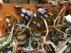
And finally we have the Phono section and Loudness board.

Photo Mar 09, 4 18 07 PM.jpg

Photo Mar 09, 4 18 23 PM.jpg

Phono board:
C101/C201 - 3.3uf/25v electrolytic capacitor
C102/C202 - 33uf/10v electrolytic capacitor
C103/C203 - 220pf/50v ceramic capacitor
C104/C204 - wire bridge
C105/C205 - 33pf/50v ceramic capacitor
C106/C206 - 0.0015uf/50v mylar capacitor
C107/C207 - 0.0056uf/50v mylar capacitor
C108/C208 - 0.47uf/50v electrolytic capacitor
C109/C209 - 0.001uf/50v mylar capacitor
C501 - 47uf/10v electrolytic capacitor
C502/C503 - 220uf/25v electrolytic capacitor
R503 - 3.3K 1/2 watt carbon comp resistor

Loudness board:
C191/C291 - 0.068uf/50v mylar capacitor
C192/C292 - 0.068uf/50v mylar capacitor
C193/C293 - 220pf/50v ceramic capacitor
C194/C294 - 220pf/50v ceramic capacitor
 
Made a little progress the last few days. I pulled all the wire bundles away from the chassis, removed the backplate and also unbolted the transformer and main caps to allow a thorough cleaning of the base. Now it's nice and clean!

Photo Mar 16, 1 40 26 PM.jpg

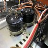
And with new caps installed. Much shorter than the originals but the perfect diameter for the original clamps.

Photo Mar 17, 12 55 20 PM.jpg

All the wires were thoroughly cleaned from all the smokers dust and sticky nicotine residue. They were really gross.

Photo Mar 16, 1 20 03 PM.jpg

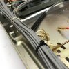
And the factory string wire ties were replaced with zip ties.

Photo Mar 17, 2 43 19 PM.jpg

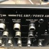
Once that was done I reinstalled the backplate and finished up the back of the unit by polishing the RCA jacks which were downright disgusting. Some Flitz metal polish, a drill and dozens of q-tips later they look amazing. Here's a little before/after comparison. The power amp inputs are clean and the preamp outputs are still not touched.

Photo Mar 17, 2 13 51 PM.jpg
 
Feeling like I made some great progress this weekend. Tackled the amp board first just so I can button up the back half of the amp.

Here you'll see how dirty the board was beforehand and how it looks once cleaned.

Photo Mar 18, 12 25 34 PM.jpg

Photo Mar 18, 12 28 41 PM.jpg

And here is a pic of the finished amp board.

Photo Mar 19, 9 23 01 AM.jpg

Along with one of the amp board/output heatsink assembled returned to the chassis.

Photo Mar 19, 12 04 14 PM.jpg

Output transistors are the originals. They all tested fine. Installed new mica and freshened up the thermal paste.

The amp board received all new caps including films & ceramics, some new resistors that were either attacked with glue or carbon comps, new diodes and new transistors. Bourns trimmers replace the original open frame trimmers. I also had some tubing lying around from a recent Pioneer SX-828 build so I used some of it to freshen up the tubing around those goofy protection devices. The old stuff was yellowed and disgusting.

Also forgot to mention when putting the back panel together I pulled apart the normal/separate switch and cleaned it thoroughly inside. Wasn't as dirty as I expected but any type of slide switch usually needs a good cleaning, more than a spray of deoxit can do from the outside. As I move to the front panel controls I'll be pulling all those switches apart as well to make sure they're in good working order.

Again, if anyone has ideas for a better protection system than those goofy spring metal light things I'm all ears.
 
Nice cleanup! The wires, bottom plate, and RCA jacks are especially nice.So you apply metal polish on the tip, secure the tip on the drill chuck and twist away?
 
So you apply metal polish on the tip, secure the tip on the drill chuck and twist away?

Pretty much. The applicator tip might be good for 1-2 jacks before it self destructs. Then you go back with clean ones to wipe off the polish and create the shine. Those can tear up quickly as well. Totally worth it for that like new look.
 
Very nice work you have done there, lots of useful information for others with TA-1150's also. l really like those early Sony's.
 
Who knows, the protection might be better than a relay. Maybe they will go open before some of the more conventional protection circuits. Is there a limiter circuit listed in the manual? The TA-3200F Sony power amp I restored had several protection areas. And together they did save the amp from catastrophic cascade failure. Even with burnt resistors it still sounded good before the restore. It has fuses, thermal protection on the outputs and a pretty healthy limiter circuit that saved the amp from the abuse it had received. If it gets over driven the limiter shunts some power to ground. Hard on the resistors, but cheaper to replace a few resistors that outputs and drivers, ect.
 
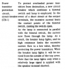
No mention of any additional limiter circuits in the manual. I have attached a clipping of how the bi-metal circuit breakers work. I'm happy to go with it. Just never encountered that sort of protection and was curious as to it's effectiveness. With all new parts and a keen understanding not to short the speaker wires I'm not expecting any trouble.

Screen Shot 2017-03-21 at 4.28.54 PM.png
 
Ah, ok. Not horrible. Do, you have a dim bulb tester? Handy when turning on equipment you know nothing about. If something is shorted the bulb will burn bright while keeping high current from reaching the equipment and causing more damage. I have a pair of Bose 301 series lll's that use a small light bulb to protect the tweeters. Restricts power at high volumes. It looks like a nice simple output and speaker protection.
 
Definitely have a DBT. Use it before I power up anything for the first time and then again after any work is done. This unit was fine from the get go.
 
Mburas Great restoration. Good pics. To help everyone else with this amp, post the schematic up on the docs section of the website. I think HiFi engine could use your latest schematic.
 
Almost forgot I had this thread going. Oops!

All is done now. The preamp board & phono board received the same treatment as the amp - all new capacitors including films & ceramics, new transistors & new resistors when carbon comps were present. I did find 3 items that needed to be on my original list for the preamp.

C532 is a 47uf/10v electrolytic
C536 is a 47uf/25v electrolytic
Q501 is a 2SC634 transistor

Here are the finished board.
FullSizeRender.jpg FullSizeRender.jpg

On the loudness board I was originally going to replace the 4 films (personal choice, not bad) but noted they are definitely not worth the effort. Multiple wire wrap posts are in the way and the post base is soldered below the wrap, not on the other side of the board, so removing them would destroy the original wrap. Nah.

I'll throw up some cleaned up outside pics in a bit.
 
As promised here are the finished photos. The faceplate & buttons/knobs cleaned up really nice.

IMG_0011.JPG IMG_0012.JPG

My initial impression is that the restoration helped enhance the already good soundstage and further defined highs, lows and mids which were muddy and/or crunchy before. With the tone controls set at midway there's definitely too much treble. I've turned it down to 1/4 while listening to most music. For only 35wpc (4 ohm speakers) this thing packs a huge punch. Much bigger than I expected. We'll see if the amp or my ears break in a little more and get used to the treble heavy sound.

Oh, and what everyone says about the volume is true. This thing goes from zero to very loud in no time at all. Maybe it's the vertical volume control that's deceiving. Not sure. Definitely a keeper....until I find the next best thing. :D
 
Back
Top Bottom