The Ultimate Switcher – User Guide
Concept and Overall Operation
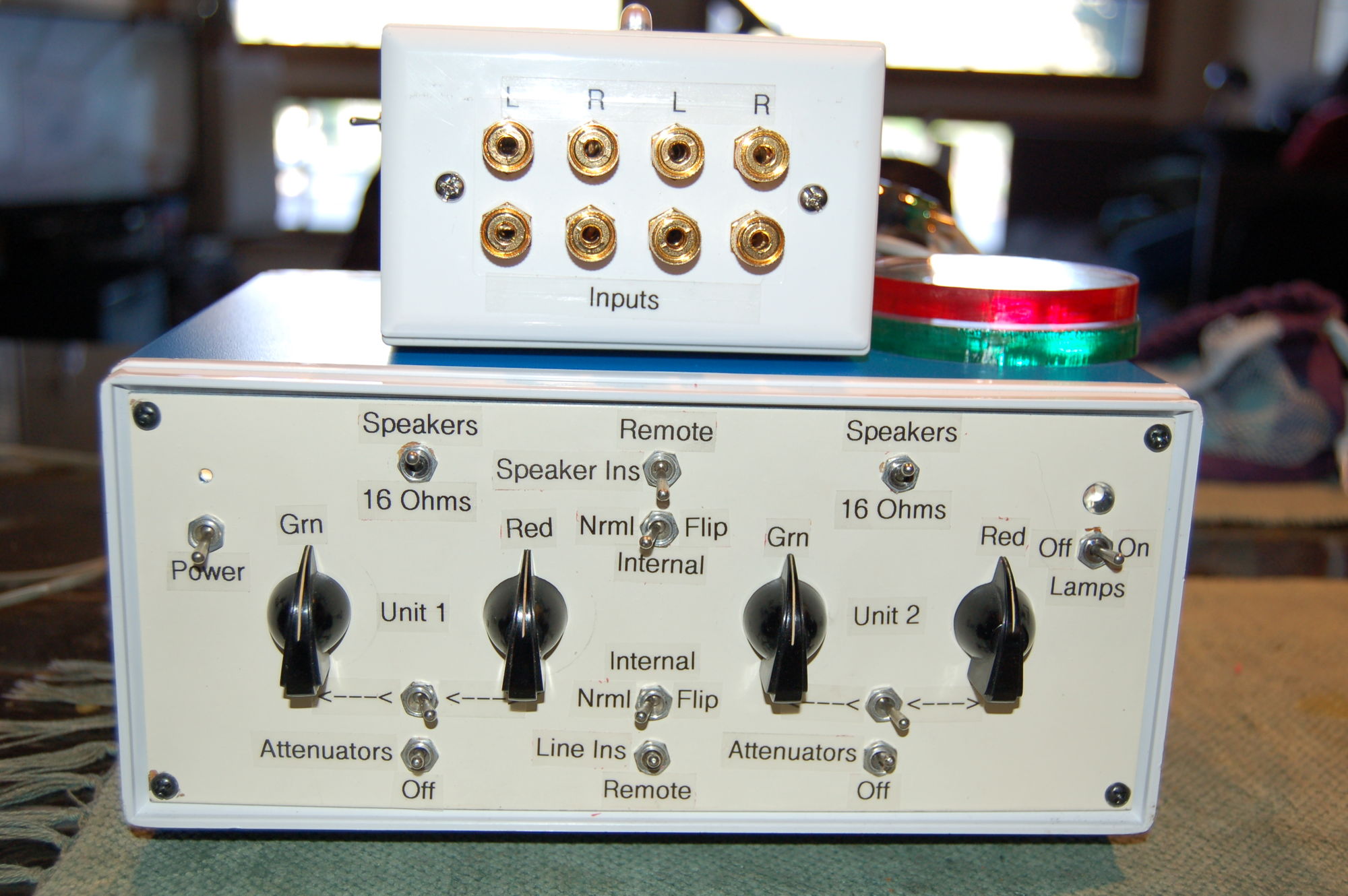
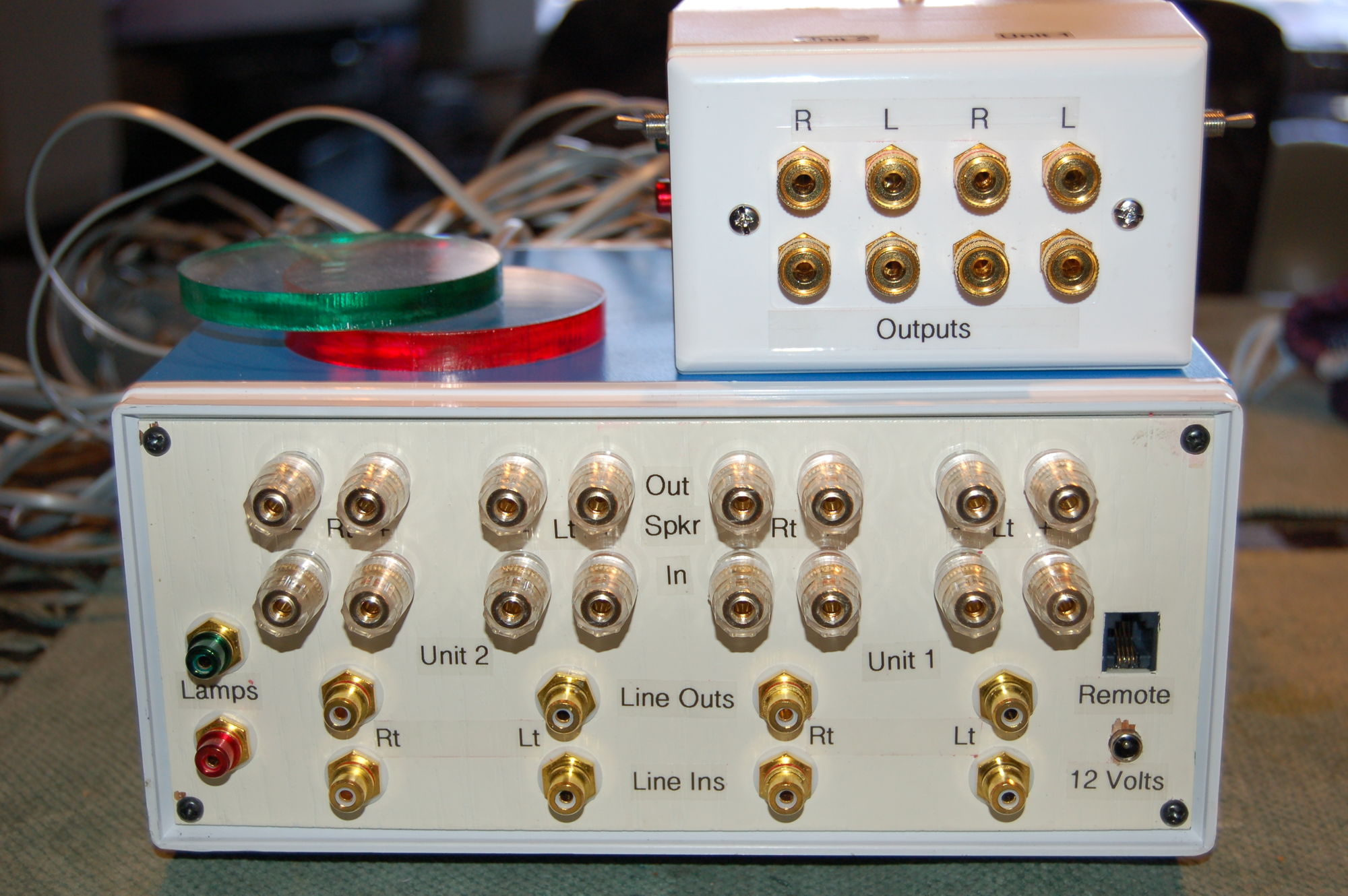
The Ultimate Switcher (TUS) allows the user to switch two separate amplifiers between two separate pair of speakers. This can be increased to four amps and four pair of speakers (in pairs) when using the remote amp/speaker attachment. (Alternatively, the remote amp/speaker attachment may be used to distance the amps/speakers from the operations’ area.) Additionally, the user can switch between two line level signals thereby allowing the user to match the volume levels when switching between two systems/speakers/components. Refer to the pictures when reading the text
TUS is divided into two sections (
Unit 1 &
Unit 2) each with its own set of line level and speaker terminals. The switching process is implemented via wireless remote when
Remote is selected for either the
Line Ins and/or
Speaker Ins. In
Grn (default) mode, the signal for each unit passes through the switcher unaltered as to its destination. In
Red mode the line level and speaker input terminals from
Unit 1 feed the output terminals of
Unit 2 and vice versa. Green and red “tell tail” lamps can be switched (
Off Lamps On) on to display the mode of the switcher or which piece being switched on/off. These may also be left off for “blind” audience testing, though the console continues to display the mode.
In addition to switching units, the line level connections also allow the user to attenuate the volume of a component. When the
Attenuators are in the
Off mode, they are by-passed from the system. When turned on and set to
<---<, the
Grn attenuators are implemented both when not switching (Grn mode) and switching (Red mode) units. When set to
<---> the
Grn attenuators are implemented when not switching (Grn mode) and the
Red attenuators are implemented in the switched position (Red mode).
When
Remote is deselected (
Internal selected) the
Nrml position will allow the
Line Ins/
Speaker Ins for each unit to pass through the switcher unaltered as to their destination
regardless of what the remote selects or tell tails show (console operator override). Similarly,
Flip allows the console operator to send the inputs from
Unit 1 to
Unit 2, and vice versa,
regardless of what the remote selected or tell tails show.
Finally the
Speakers/
16 Ohms switches (also on the sides of the remote amp/speaker attachment) replace the
Spkr Out terminals with 16 ohm, 100 watt load resistors. These can be implemented when a second set of speakers is not being tested (e.g., two amps with one set of speakers while applying a load to the second amp), or to override (quiet) as second set of speakers when one is testing two amplifiers through one set of speakers, but two sets are connected. However, if one is testing a tube amp and is unsure that the tube amp can withstand
no load for the milliseconds that the relay is open as it takes to fire, a 100 ohm resistor can be attached across the
Spkr In terminals. On a 16 ohm load, this would reduce the overall impedance to 13.8 ohms (7.4 ohms for an 8 ohm load) and should have little effect on the sound.