

You are using an out of date browser. It may not display this or other websites correctly.
You should upgrade or use an alternative browser.
You should upgrade or use an alternative browser.
Speaker pop on shut off Sanyo JCX2900
- Thread starter curtisw99
- Start date
If you have some spare time...
With MM you see spike at about 100-200mV at power off. Try setting mute on then power off, do you still see some mV??? Certain the mute will attenuate the pop, hopeful that the mute circuit/R420(220) will speed up the relay.
edit
Pure BS, the mute switch causes the relay to drop out so you will see no mV
If this works out then consider replacing mute timing cap C412 (47uf) with 33uf but you run the risk of turn ON pops.
edit try the 33uf cap, should speed up the relay, ignore any power on pop for time being.
Yeah, this one is doing my head in...
edit
Relay supply comes from D903 and is filtered by C917(470uf) try 330uf or even 220uf
edit
Pure BS, the mute switch causes the relay to drop out so you will see no mV
If this works out then consider replacing mute timing cap C412 (47uf) with 33uf but you run the risk of turn ON pops.
edit try the 33uf cap, should speed up the relay, ignore any power on pop for time being.
Yeah, this one is doing my head in...
edit
Relay supply comes from D903 and is filtered by C917(470uf) try 330uf or even 220uf
Last edited:

I was thinking about that cap as well, was going to ask what you thought about changing the value.If you have some spare time...
With MM you see spike at about 100-200mV at power off. Try setting mute on then power off, do you still see some mV??? Certain the mute will attenuate the pop, hopeful that the mute circuit/R420(220) will speed up the relay.
edit
Pure BS, the mute switch causes the relay to drop out so you will see no mV
If this works out then consider replacing mute timing cap C412 (47uf) with 33uf but you run the risk of turn ON pops.
edit try the 33uf cap, should speed up the relay, ignore any power on pop for time being.
Yeah, this one is doing my head in...
edit
Relay supply comes from D903 and is filtered by C917(470uf) try 330uf or even 220uf
I will try that
First, I think I will replace all the diodes in the protection circuit and clean all the relays.
Does C918 also filter D903?If you have some spare time...
With MM you see spike at about 100-200mV at power off. Try setting mute on then power off, do you still see some mV??? Certain the mute will attenuate the pop, hopeful that the mute circuit/R420(220) will speed up the relay.
edit
Pure BS, the mute switch causes the relay to drop out so you will see no mV
If this works out then consider replacing mute timing cap C412 (47uf) with 33uf but you run the risk of turn ON pops.
edit try the 33uf cap, should speed up the relay, ignore any power on pop for time being.
Yeah, this one is doing my head in...
edit
Relay supply comes from D903 and is filtered by C917(470uf) try 330uf or even 220uf
Yes C918(-ve rail) and C917(+ve rail) performs smoothing of D903 output.Does C918 also filter D903?
It’s not the relay board. Every diode on the relay board checked good (out of circuit)Yes C918(-ve rail) and C917(+ve rail) performs smoothing of D903 output.
The relay contacts looked pristine
I’ll try different cap values tomorrow.
Were those DC offset numbers at shutoff that I posted normal? Could it be the differential pair? Or the outputs?I've been distracted, will try and have a look later in the day
Post #58, no pop if pre/main jumpers removed so preamp issue not diff pair or outputsCould it be the differential pair? Or the outputs?
Post #111 200mV dc spike at power off L&R channelsWere those DC offset numbers at shutoff that I posted normal?
Normal? Probably, it takes some time for the protection caps to run down
Significant? Maybe, 200mV equates to 0.005W. "Problem" is your MM is somewhat slow and probably takes an average reading so maybe the spike is 4-500mV, but into say 90dB speakers...
Bumping up the rails caps appeared to have no affect.
Something I've just noticed...
Schematic shows "Muting Switch" S14-1 and S14-2 which we've previously talked about (R420 220 or 1k...) which appears to run down the protection circuit so relay releases.
The schematic also shows "Muting Switch" S6-1 S6-2 which looks more traditional, additional 47k... to audio path
I had incorrectly thought that S14 was a means to mute audio. Need to workout how S14 is activated.
I was going to mention to check coupling caps C551, C651, C557, C657, C562, C662, C565, C665, C591, C691.
These are supposed to suppress dc, fairly sure you did a recap...
S14 is on the power switch boardNeed to workout how S14 is activated.
When on S14-1 releases the relay discharging C412 through R420 to GND
S14-2 has a connection to tab "7" which goes to FM stage which is grounded when on
Need to take a look at power switch, can you post a pix of the old switch, also great if you can post pix of switch board solder side.
Last edited:
Here are pictures of the switch boardS14 is on the power switch board
When on S14-1 releases the relay discharging C412 through R420 to GND
S14-2 has a connection to tab "7" which goes to FM stage which is grounded when on
Need to take a look at power switch, can you post a pix of the old switch, also great if you can post pix of switch board solder side.
Are there components missing, or in the wrong spot?, see my red arrows in the picture.
Switch board has been worked on by someone previous to me.
I can’t find a wiring diagram in the manual.
Can you compare to yours?
Attachments
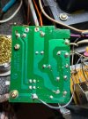

Everything but the tuner is recappedPost #58, no pop if pre/main jumpers removed so preamp issue not diff pair or outputs
Post #111 200mV dc spike at power off L&R channels
Normal? Probably, it takes some time for the protection caps to run down
Significant? Maybe, 200mV equates to 0.005W. "Problem" is your MM is somewhat slow and probably takes an average reading so maybe the spike is 4-500mV, but into say 90dB speakers...
Bumping up the rails caps appeared to have no affect.
Something I've just noticed...
Schematic shows "Muting Switch" S14-1 and S14-2 which we've previously talked about (R420 220 or 1k...) which appears to run down the protection circuit so relay releases.
The schematic also shows "Muting Switch" S6-1 S6-2 which looks more traditional, additional 47k... to audio path
I had incorrectly thought that S14 was a means to mute audio. Need to workout how S14 is activated.
I was going to mention to check coupling caps C551, C651, C557, C657, C562, C662, C565, C665, C591, C691.
These are supposed to suppress dc, fairly sure you did a recap...
Checked all the voltages in the manuals.
Only transistor voltages are provided.
All those check out.
I’m currently stumped.
I think i’ll get a replacement power switch and see what that does.
I have read this is common
Negative on the triac.
Look carefully at the schematic of the protection circuit. This kinda caught me by surprise. There is a set of NC contacts on the power switch that ground the relay drive when the power switch is moved to off. When turning the unit off, be decisive about it. You may have to take that switch apart and clean those contacts with some Brasso or Flitz. Make sure you get all the residue out.
If this works, it will be the first time I've seen fixing a power switch correct a "pop" condition.
For sure, check the switch. I have had problems with other Sanyo switches (P55, C55) and recently had a C55 in a system that starting loud popping. Traced it to the switch and even though the contact resistance did not appear terrible, cleaning the switch solved the problem. I would have replaced it, but on this unit, the switch advertised as a drop-in (on ebay) did not fit the board. So I attempted cleaning instead and it solved the issue.
I put in a new switch and no changeFor sure, check the switch. I have had problems with other Sanyo switches (P55, C55) and recently had a C55 in a system that starting loud popping. Traced it to the switch and even though the contact resistance did not appear terrible, cleaning the switch solved the problem. I would have replaced it, but on this unit, the switch advertised as a drop-in (on ebay) did not fit the board. So I attempted cleaning instead and it solved the issue.
But it looks like someone was in there before and might have changed something.
I need pictures of a switch board from someone who doesn’t have the pop.
Last edited:
Please check where the purple and black wires (wire wrap post) terminate. Looking for purple terminating near R420, black probably GND. Thinking the large red circle is S14.
With switch off, measure resistance between contacts in red circle, expect short...
With switch off, measure resistance between contacts in red circle, expect short...
Attachments
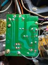
My wire colors all match your text.Please check where the purple and black wires (wire wrap post) terminate. Looking for purple terminating near R420, black probably GND. Thinking the large red circle is S14.
With switch off, measure resistance between contacts in red circle, expect short...
Measuring from A to B ( see picture):
With switch off, I get 2.5 ohm
Switch on, I get short.
Attachments
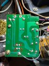
Last edited:
Hopefully a typo???With switch off, I get 2.5 ohm
Switch on, I get short.
With switch ON expect OPEN/OL/MegOhms....
2.5ohms is close enough to short
Yeah typoHopefully a typo???
With switch ON expect OPEN/OL/MegOhms....
2.5ohms is close enough to short
When on it’s open
Last edited:
OK, that's switch S14, the purple wire should go back to R420, you previously confirmed near short on R420 when power switch off.When on it’s open
I feel we are no closer to root cause, maybe some fresh eyes needed, some observations/things tried
- Pop immediately at power off, no pop when pre/main links removed
- power switch and snubbers replaced
- pop remains if power off at wall/connection board rather than amp
- additional rails capacitance to preamp supplies has no affect, pop remains
- reducing mute timing cap (C412) to speed up p-off time has no effect
- amp has been recapped
I found the root cause of the pop. The relay is opening too fast. There needs to be a delay before the relay opens at shutoff.OK, that's switch S14, the purple wire should go back to R420, you previously confirmed near short on R420 when power switch off.
I feel we are no closer to root cause, maybe some fresh eyes needed, some observations/things tried
- Pop immediately at power off, no pop when pre/main links removed
- power switch and snubbers replaced
- pop remains if power off at wall/connection board rather than amp
- additional rails capacitance to preamp supplies has no affect, pop remains
- reducing mute timing cap (C412) to speed up p-off time has no effect
- amp has been recapped
I taped the relay closed and the pop does not happen at shutoff. So somehow, this relay should have a delay that is not happening.
So the question is:
Why is it not delayed and how can I get the relay to stay closed longer?
Attachments

Last edited: