• The move to the new server is done. There are some software and database maintenance updates in process. This has us passing the hat around to help out. We appreciate any donations. Seriously, even a dollar helps. The payment page may be found here - https://www.audiokarma.org/support.html

Speaker pop on shut off Sanyo JCX2900

More questions than answers...

Looks like someone has been there before, trying to fix the same issue???
That solder joint is not real good, Also the break in the casing... The cap is almost certainly functional but...
Also appears to be an negative sign on the cap. Would have been happier to see a X1/Y1 film cap.
As above caps are on the same tabs so likely wired correctly.

If it was me, I'd change them out and go for the 0.047uf, ok this breaks the golden rule of going with whats installed
No change. Still pops.
How can I test if the transistors on the power supply are working well?

The Base and emitter voltages are almost exactly to the manual, but the collector voltages are low
One is 4.5v low q905
Other is 3.6v low q902
Also
Collector voltages 4.5v low on q906
Collector voltage 4.6v low on q903
Collector voltage 4v low on q901
 
Last edited:
How can I test if the transistors on the power supply are working well?
Look at the +/- rails, wanting to see symmetry, eg +/-50Vdc or close to. Also check the ripple on both rails. The ripple may be different for the +ve and -ve rails depending on the load (how many circuits/stages) are connected, eg the MIC stage only draws from the +ve rail (point C)

Check rails at points A, C, D, B
pin 6 and pin 12 (both for tuner)

The Base and emitter voltages are almost exactly to the manual, but the collector voltages are low
My service manual does not give guiding values for psu transistors...

The 4V abouts difference is at the annoying level, need to question/be comfortable with

The collectors are on the input side of the regulator, the emitters on the output side. If emitter voltages are symmetrical and in spec then thats a good start. Normally take guiding values with a grain of salt, late production changes do occur

Also keep in mind that these voltages eventually come from mains power (100Vac?) and during the course of the day the mains can/does sag. In AU the operating spec for mains is 230Vac +/-10%
 
Look at the +/- rails, wanting to see symmetry, eg +/-50Vdc or close to. Also check the ripple on both rails. The ripple may be different for the +ve and -ve rails depending on the load (how many circuits/stages) are connected, eg the MIC stage only draws from the +ve rail (point C)

Check rails at points A, C, D, B
pin 6 and pin 12 (both for tuner)


My service manual does not give guiding values for psu transistors...

The 4V abouts difference is at the annoying level, need to question/be comfortable with

The collectors are on the input side of the regulator, the emitters on the output side. If emitter voltages are symmetrical and in spec then thats a good start. Normally take guiding values with a grain of salt, late production changes do occur

Also keep in mind that these voltages eventually come from mains power (100Vac?) and during the course of the day the mains can/does sag. In AU the operating spec for mains is 230Vac +/-10%
When I compare the voltages on both sides they differ by 0.7v
Voltage to tuner is 12.5v
 
When I compare the voltages on both sides they differ by 0.7v
Voltage to tuner is 12.5v
That appears reasonable

Initial theory was the relay was not closing fast enough.
Later theory was some noise associated with turn off ie, power switch snubber.

Need to have a rethink...

When the amp is on, do you get any strange pops when working any of the switches??
 
That appears reasonable

Initial theory was the relay was not closing fast enough.
Later theory was some noise associated with toff ie, power switch snubber.

Need to have a rethink...

When the amp is on, do you get any strange pops when working any of the switches??
This thing has never had poppy or scratchy controls
But
I had a similar thought, so just in case, last month, I went in and re-cleaned everything ; including disassembling the volume control.
No change
 
Both channels affected might suggest power supply (or maybe just relay not opening fast enough lol...)
Maybe take a punt, add some extra capacitance to the preamp +/- rails, this is not a fix, more so a fishing trip, hopefully the rails should stay "up" a bit longer giving the relay a chance to open.

Whatever you have handy 220uf - 1000uf 35-63V or whatever.
One cap positive terminal to point E in schematic (R921 150ohms) -ve terminal to Pin 11 or point G (GND)
Other cap negative terminal to point F(R923, 150ohms) and +ve terminal to GND

Your schematic may be different, if any doubt post screenshot of schematic.

Look at connecting the caps wherever easiest, maybe solder side.
Certainly dbt power up without speakers, connect meter to speaker posts 20Vdc scale
 
Both channels affected might suggest power supply (or maybe just relay not opening fast enough lol...)
Maybe take a punt, add some extra capacitance to the preamp +/- rails, this is not a fix, more so a fishing trip, hopefully the rails should stay "up" a bit longer giving the relay a chance to open.

Whatever you have handy 220uf - 1000uf 35-63V or whatever.
One cap positive terminal to point E in schematic (R921 150ohms) -ve terminal to Pin 11 or point G (GND)
Other cap negative terminal to point F(R923, 150ohms) and +ve terminal to GND

Your schematic may be different, if any doubt post screenshot of schematic.

Look at connecting the caps wherever easiest, maybe solder side.
Certainly dbt power up without speakers, connect meter to speaker posts 20Vdc scale
I’m at the DBT and multimeter stage in my learning curve. I’ve gotten several receivers running with just that, but this thing is another animal.
What would I do if I had an oscilloscope?

There’s ~13mV DC at the speaker terminals

I will try the capacitors this weekend
 
What would I do if I had an oscilloscope?
First confirm relay is opening within an acceptable time so we could rule out the slow relay theory.
Monitor the collapse of the +ve/-ve power supply rails, identify which rail is at fault (if any)
There’s ~13mV DC at the speaker terminals
What does the voltage jump to when you power off? This would be a useful baseline when you add the extra caps
 
First confirm relay is opening within an acceptable time so we could rule out the slow relay theory.
Monitor the collapse of the +ve/-ve power supply rails, identify which rail is at fault (if any)

What does the voltage jump to when you power off? This would be a useful baseline when you add the extra caps
Did a study
For each channel I had a realistic minimus 7 in the other channel so I could hear the pop.
I would wait for the DC to hit steady state and then turn it off.
Results:
LH: steady state DC ~9.3mv
I did 5 shutoffs and recorded the peak DC
153mv
154mv
123mv
73mv
188mv

RH: steady state DC ~8.3mv
Peak DC for shutoff for 5 tries
110mv
175mv
154mv
141mv
97mv
 
  • Like
Reactions: mbz
Did a study
For each channel I had a realistic minimus 7 in the other channel so I could hear the pop.
I would wait for the DC to hit steady state and then turn it off.
Results:
LH: steady state DC ~9.3mv
I did 5 shutoffs and recorded the peak DC
153mv
154mv
123mv
73mv
188mv

RH: steady state DC ~8.3mv
Peak DC for shutoff for 5 tries
110mv
175mv
154mv
141mv
97mv
P.S. I see the same spike at turn on, but the relay is open at that point

Is this related to the pop?
 
Much the same for both channels, say 200mV or 0.005W!
Yeah this depends on how "fast" you meter is, I've done similiar tests and seen xxVolts!
 
OK so no pop when pre/main links removed, try a similiar approach, lift one leg or remove R551(560) and R651(560). This is the input to the preamp, expect amp to still pop. Then try lifting R590 (2k2) and R690(2k2) probably no pop
 
P.S. I see the same spike at turn on, but the relay is open at that point

Both channels affected might suggest power supply (or maybe just relay not opening fast enough lol...)
Maybe take a punt, add some extra capacitance to the preamp +/- rails, this is not a fix, more so a fishing trip, hopefully the rails should stay "up" a bit longer giving the relay a chance to open.

Whatever you have handy 220uf - 1000uf 35-63V or whatever.
One cap positive terminal to point E in schematic (R921 150ohms) -ve terminal to Pin 11 or point G (GND)
Other cap negative terminal to point F(R923, 150ohms) and +ve terminal to GND

Your schematic may be different, if any doubt post screenshot of schematic.

Look at connecting the caps wherever easiest, maybe solder side.
Certainly dbt power up without speakers, connect meter to speaker posts 20Vdc scale
I’ll try the capacitor as well

My wiring diagram has capital and lower case E and G (e and g)

See attached picture

Do you mean big “E” or little “e” and big “G” or little “g”?
 

Attachments

  • IMG_2456.jpeg
    IMG_2456.jpeg
    241.2 KB · Views: 3
Last edited:
Do you mean big “E” or little “e” and big “G” or little “g”?
Yeah, there is a lack of consistency between schematic and board layout.

Schematic is the logical connection diagram.
Board layout/track work is actual/physicalconnection diagram.

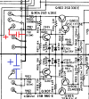
attached psu shows 2 new caps logical connection
psu2 shows physical connection, problem is I cannot see the tracks (poor manual quality)

The -ve terminal/solder blob of C923 is GND, both caps connect to this point.
You need to check the tracks, you should see a track connecting R920 and R921
Likewise there will be a track connecting R922 and R923.

We are interested in the other end of R921 and R923.

So "red" cap, +ve terminal to R921 solder blob (without track to R920), -ve terminal to C923 -ve blob
"blue" cap -ve terminal to R923 solder blob(without track to R922), +ve terminal to C923 -ve blob

I am guessing the connection end in psu2. You need to check
 

Attachments

  • psu.png
    psu.png
    120.7 KB · Views: 3
  • psu2.png
    psu2.png
    161.6 KB · Views: 3
Yeah, there is a lack of consistency between schematic and board layout.

Schematic is the logical connection diagram.
Board layout/track work is actual/physicalconnection diagram.

attached psu shows 2 new caps logical connection
psu2 shows physical connection, problem is I cannot see the tracks (poor manual quality)

The -ve terminal/solder blob of C923 is GND, both caps connect to this point.
You need to check the tracks, you should see a track connecting R920 and R921
Likewise there will be a track connecting R922 and R923.

We are interested in the other end of R921 and R923.

So "red" cap, +ve terminal to R921 solder blob (without track to R920), -ve terminal to C923 -ve blob
"blue" cap -ve terminal to R923 solder blob(without track to R922), +ve terminal to C923 -ve blob

I am guessing the connection end in psu2. You need to check
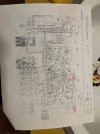
Got it all wired up
Checked for all continuity before I fired up. Used 470uf 63v
No shorts on the dim bulb
No change in pop; same as always
Still pops in both channels and I see similar spikes in mv at shutoff
 

Attachments

  • IMG_2461.jpeg
    IMG_2461.jpeg
    326.7 KB · Views: 2
  • Like
Reactions: mbz
Used 470uf 63v
Should have lengthed the graceful period so would expect a weaker pop.

Running out of ideas,

What happens if you plug the amp into a power board and power down using switch on power board rather than amp power switch?
 
Should have lengthed the graceful period so would expect a weaker pop.

Running out of ideas,

What happens if you plug the amp into a power board and power down using switch on power board rather than amp power switch?
If I switch off at the dbt, it pops
 
  • Like
Reactions: mbz
Back
Top Bottom