• The move to the new server is done. There are some software and database maintenance updates in process. This has us passing the hat around to help out. We appreciate any donations. Seriously, even a dollar helps. The payment page may be found here - https://www.audiokarma.org/support.html

Speaker pop on shut off Sanyo JCX2900

After power up, allow 5 or so seconds for transients to settle then D419 anode should be +1.2Vdc (Q431, Q432 Vbe). D419 cathode should be about 4.7 + 1.2V = +5.9V (depending on the actual zener voltage(4.7, 4.6, 4.5,,,)
There will be slight drift (xxmV?) with mains but supply is regulated (Q902,3,4, D...), the volt drop across the zener should be roughly constant at about 4.7V.

Previous posts indicate abnormal zener behaviour.

With a 500mW item a 4.7V zener can handle 106mA, plenty for this circuit, R419 would cripple the cathode voltage for any slight increase in current.

Suggest focus on D419, if possible replace with another 500mW item.
If you have a dbt then dbt power up and if possible monitor D419 anode to GND and cathode to GND (2xmultimeter). Wanting to see stable cathode voltage at about 5.9V allow xxmV drift, anode voltage +1.2V expected.

If cathode voltage is less than 4.5V than anode should be near zero, maybe xxxmV leakage???

If cathode voltage is low and unstable then need to look elsewhere...
I think the problem is the relay closes at the same time as the power switch. My other receivers have a delay.

Which is the timing capacitor?
 
Why is there a relay delay at turn on, but no delay at turn off?
I misunderstood...
At power off we want the relay to open immediately/without delay to prevent any power off "transients" from finding their way to the spkrs. The +ve and -ve power rails collapse at different rates, this causes a DC offset and subsequent pop in spkrs if relay does not open quickly
 
I think the problem is the relay closes at the same time as the power switch. My other receivers have a delay.
Wanted behaviour is,
at power on there should be a 3-6second delay before relay closes, gives amp time to stabilize.
at power off the relay should open as quickly as possible/"immediately"
 
I misunderstood...
At power off we want the relay to open immediately/without delay to prevent any power off "transients" from finding their way to the spkrs. The +ve and -ve power rails collapse at different rates, this causes a DC offset and subsequent pop in spkrs if relay does not open quickly
Are you sure?
My kenwood 5030 and realistic 2080 have a noticeable delay between switch off and relay open and they have no pop.
 
Are you sure?
99.9%

The ideal case is for the relay to open immediately
In reality it will take some time (<1 sec?) for C412 voltage to drop

Maybe too much detail...
At power off we want the relay drive transistor (Q432) to turn off quickly, ie Q432 Vb < 0.3Vdc abouts
Working back, it means we need Q431 to begin shut down, Vb < 0.7Vdc

Q431Vb comes from the zener D419 which should stop conducting ("leaking" voltage to Q431b) when the cathode voltage drops below 5.9Vdc abouts

Looking at C412 discharge...
R420 is related to the mute switch.
It looks like discharge is via D417 R432, R433.

Have you tested/replaced D417?


I think the problem is the relay closes at the same time as the power switch.
Are you saying the relay opens immediately at power off?
In which case you will have no pop caused by the power amp. Maybe some arching of relay contacts????
 
99.9%

The ideal case is for the relay to open immediately
In reality it will take some time (<1 sec?) for C412 voltage to drop

Maybe too much detail...
At power off we want the relay drive transistor (Q432) to turn off quickly, ie Q432 Vb < 0.3Vdc abouts
Working back, it means we need Q431 to begin shut down, Vb < 0.7Vdc

Q431Vb comes from the zener D419 which should stop conducting ("leaking" voltage to Q431b) when the cathode voltage drops below 5.9Vdc abouts

Looking at C412 discharge...
R420 is related to the mute switch.
It looks like discharge is via D417 R432, R433.

Have you tested/replaced D417?


Are you saying the relay opens immediately at power off?
In which case you will have no pop caused by the power amp. Maybe some arching of relay contacts????
The detail is great; keep it coming

D417 is new, but the old one tested good. New diode measured good before it went in

Relay opens immediately (matches the switch)
 
Relay opens immediately (matches the switch)
And you are still getting a pop through the spkrs at power off?????
Also means the protect circuit is working as it should.

If you are still getting a pop at power off then???? maybe power rails are "sick" with one rail collapsing immediately or???
 
And you are still getting a pop through the spkrs at power off?????
Also means the protect circuit is working as it should.

If you are still getting a pop at power off then???? maybe power rails are "sick" with one rail collapsing immediately or???
Still pops the same at shutoff. No improvement since the start of this process.

I’ve been reading about the rails collapsing unevenly; what are the possible causes?
Only old caps are in the tuner and the 4 big filters. All other caps are new (all measured before install)
Or is it semi conductors that cause the uneven collapse ?
 
I’ve been reading about the rails collapsing unevenly; what are the possible causes?
Most probable cause is tired main caps

I'm sceptical that this is a "rails collapse" issue since the relay releases immediately at power off.
Anyway, by the numbers, to test for rails collapse monitor the voltage at the +ve and -ve rails at the main filter caps. Ideally you would use an oscilloscope however two volt meter/MM would also work. If you only have 1 MM then do one rail at a time. At power off monitor the voltage collapse, we are only interested in the first second, compare the +/- rail voltage after one second of power off. Also pay extra attention to any voltage spike possibly coming from power switch.

This is possibly an issue with faulty relay where contacts have been welded but this would give a pop at power on. Alternatively there is some arcing in the power switch that is finding its way into the power supply.
 
Most probable cause is tired main caps

I'm sceptical that this is a "rails collapse" issue since the relay releases immediately at power off.
Anyway, by the numbers, to test for rails collapse monitor the voltage at the +ve and -ve rails at the main filter caps. Ideally you would use an oscilloscope however two volt meter/MM would also work. If you only have 1 MM then do one rail at a time. At power off monitor the voltage collapse, we are only interested in the first second, compare the +/- rail voltage after one second of power off. Also pay extra attention to any voltage spike possibly coming from power switch.

This is possibly an issue with faulty relay where contacts have been welded but this would give a pop at power on. Alternatively there is some arcing in the power switch that is finding its way into the power supply.
You mean measure between ground and one side of the filter caps?
Then ground and the other side of the filter caps?
While it’s shitting down
 
Last edited:
You mean measure between ground and one side of the filter caps?
Then ground and the other side of the filter caps?
What you should see is that the filter caps are connected, more accurately the +ve of one terminal is connected to the -ve of the other, this is the GND point, you will probably see one or more black wires connected to this point. Looking at the other cap terminals, the +ve terminal is the +ve rail, -ve terminal is -ve rail. Monitor voltages at +ve and -ve rails, ie not at the shared terminals which is GND.

Simplest just to connect MM across one of the filter caps, one of the terminals is GND, repeat for other cap.
 
What you should see is that the filter caps are connected, more accurately the +ve of one terminal is connected to the -ve of the other, this is the GND point, you will probably see one or more black wires connected to this point. Looking at the other cap terminals, the +ve terminal is the +ve rail, -ve terminal is -ve rail. Monitor voltages at +ve and -ve rails, ie not at the shared terminals which is GND.

Simplest just to connect MM across one of the filter caps, one of the terminals is GND, repeat for other cap.
Will do
I have a filter cap pulled out (i was thinking the same way and am trying to find a new match)
A soon as i get it back together and measure, i will report back.
 
What you should see is that the filter caps are connected, more accurately the +ve of one terminal is connected to the -ve of the other, this is the GND point, you will probably see one or more black wires connected to this point. Looking at the other cap terminals, the +ve terminal is the +ve rail, -ve terminal is -ve rail. Monitor voltages at +ve and -ve rails, ie not at the shared terminals which is GND.

Simplest just to connect MM across one of the filter caps, one of the terminals is GND, repeat for other cap.
Had to set this aside to fix my mother in law’s turntable; I’m back at it.

checked all the voltages on the filter caps and they are within 0.5v.
I also tried new filter caps and no change.
 
Have you replaced the 2 0.047uf caps that connect across the power switch
No
Haven’t replaced those.
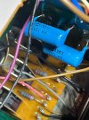
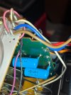
Looking at them, I think they are a different value than the manual. They look like 0.012uf
It almost looks like there used to be something else in the shorter hole

Can you tell if they are wired in correctly?
 

Attachments

  • IMG_2444.jpeg
    IMG_2444.jpeg
    197.3 KB · Views: 10
  • IMG_2445.jpeg
    IMG_2445.jpeg
    204.2 KB · Views: 8
  • IMG_2446.jpeg
    IMG_2446.jpeg
    174.8 KB · Views: 9
  • IMG_2447.jpeg
    IMG_2447.jpeg
    202.1 KB · Views: 9
That hole is in the same pad. Likely to accommodate different parts that do the same thing ( a film cap with shorter lead spacing)
 
More questions than answers...

Looks like someone has been there before, trying to fix the same issue???
That solder joint is not real good, Also the break in the casing... The cap is almost certainly functional but...
Also appears to be an negative sign on the cap. Would have been happier to see a X1/Y1 film cap.
As above caps are on the same tabs so likely wired correctly.

If it was me, I'd change them out and go for the 0.047uf, ok this breaks the golden rule of going with whats installed
 
More questions than answers...

Looks like someone has been there before, trying to fix the same issue???
That solder joint is not real good, Also the break in the casing... The cap is almost certainly functional but...
Also appears to be an negative sign on the cap. Would have been happier to see a X1/Y1 film cap.
As above caps are on the same tabs so likely wired correctly.

If it was me, I'd change them out and go for the 0.047uf, ok this breaks the golden rule of going with whats installed
It happens I have some .047uf x2
I will try them tomorrow
 
  • Like
Reactions: mbz
Back
Top Bottom