• The move to the new server is done. There are some software and database maintenance updates in process. This has us passing the hat around to help out. We appreciate any donations. Seriously, even a dollar helps. The payment page may be found here - https://www.audiokarma.org/support.html

ST70 7199 / 6GH8A amplitude vs frequency

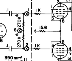
Are those the grid to bias supply resistors, or the bias supply to grid resistors? The ones going to the bias supply are what the phase inverter sees as the load. Not sure what they used on those, but anything in the 100k-330k range would be my guess. Its possible these live on the board, I've never worked on an ST-70 so I don't know where they may have hidden this.

these are 1K resistors. the wires off of the board go to an unused pin on the EL34 and the 1K resistor is bridged across that pin to the EL34 grid


Screen%2BShot%2B2015-10-05%2Bat%2B8.30.38%2BPM.png
 
Last edited:
Its the 270k resistors that will mess with how the inverter stage is loaded.
Ive got those covered, those were the 306K ones that I replaced with 1% 270k's


Interesting note....... they were both 306K within 1%........ just not 270K
 
The value and the precision of the grid leak resistors are already well within spec... I think Audiovet pointed out that the waveforms you see are a part of a feedback loop, which may or may not be indicative of an unbalanced PI.
 
Again, not wishing to rain on the parade ....

But let me first bless the parade! My best wishes to all gentlemans contributing here, not only for 2016 (made it!!!) but far into the future!

To continue: As one gets to a finer degree of balance .... there are still two EL34s following, plus the OPT. To what degree will they be matched? Not to advocate sloppiness, but there is a practical limit to what is within general spread (do you go through the whole exercise again when a tube is changed/aging?), plus good old NFB to iron matters out. Good to notice that good instruments are used here. Just keeping practically useful circumstances in picture.
 
Im going to take a minute and put the usual conversation of THD, graphs and math aside to make an observation. While I say this, I will still be doing the experiment when the 47K POTS arrive
Id replaced the two 10ohm resistors that read at 16 and 12 and put in my matched 270K's on both channels

Today I disconnected all of my test equipment (except for the multimeter on the 1.56bias)
I replaced the test equipment with my AIWA 8 OHM 3 way test speakers. They are my second favorite when you consider that I can't put my 1.5 meter tall JBL's on the test bench.
I was utterly amazed at the sound produced by this AMP. I didn't need the 331A to tell me how good it was.
3 hours I sampled songs, including a few that I know run the amp to its very limits including

Buddy Rich : birdland and caravan
Freddie Mercury : Exercises in love (a most difficult one to pull off without distortion)
MFSB: manhattan skyline
Ella Fitzgerald and duke Ellington songbook
Dire straits greatest hits (you can hear the pick scraping against the gnarled contours of the E and A strings from the lead guitar)

This AMP is as close to bone stock as it gets, as you all know, right down to the selenium rectifier, save the 6GH8A conversion. It has its own characteristics, and shortcomings,
most notably, the power transformer, and the single GZ34. The power transformer is the single biggest cause of sag

Aside from that, and with the test of the 47K's balanced, there is little more Id like to do to this amp than conduct that last change and test, and close it down.
Once my last test is done I will be moving it into a new SS chassis and replacing the 4 el43 sockets, the power/monostereo switch, and repainting the transformers.

replacing the power transformer with a 120v modern one is still up for debate.

Serenity is knowing the difference between the 'tube sound' and the 'solid state' sound. The difference is.... Every tube AMP is unique and has its own characteristic/harmonics.
No two tube AMPS sound the same, each has its own personality. No gimmick will give an AMP a better tube sound, just a different sound. Its uniqueness is in the mechanics of how different
sounds and harmonics are processed and amplified, nothing more.

J

 
I suspect you'll find that the rectifier is the bigger bottleneck than the transformer. Once you fix that, the transformer is an issue, but the rectifier is way over-worked trying to deliver the current two pairs of EL34's want at full tilt.
 
There is something to be said for the required wattage to drive speakers. In my testing, the Iphone at max volume as an input would have been way too loud on the output. I believe, and must recheck my figures, that the Iphone max input could only generate 6W maximum on each output channel. I couldnt imagine what 24 or 35 watts would produce on the output in decibels.
 
So I ran my last experiment..... its a 47K with a 2K pot
16%2B-%2B1


In an attempt to find matched vs. balance I found that this concept doesnt work, what you take off of the bottom you give to the top and the other way around. keeping it in the middle is the best way to go and there is no reason to dig any deeper.
I did replicate it being 1.1k off, which is what the right channel currently is and found that distortion does rise as you leave the matched settings. The artifact displayed on the oscope from the 311A output is a good gauge of this symptom

With that, the THD of the right channel is .07 where the left is .05. at 1khz with 6vrms I have 47Ks within 1% but would like the old looking ones and not modern looking replacements. I went with modern for the 270k's because all four needed replacing so it matched.. The 47ks are quite large in physical size and I dont have any to put in the unit.


Transformer.........

The transformer took 45 minutes to settle down, with a swing of bias reading from 1.67 to 1.56 where it stabilized over 45 minutes. While I imagine running some input would have shortened the stabilization time, im not convinced that running at 1.67 waiting for the transformer to warm up is overly practical, that said its a 117V running @ 120v
 
If you want to retain the original look and match to 1% , you could buy 20-30 carbons and hand match. They may be off spec slightly though if they match each other I don't think it'd matter much. They're cheap enough
 
If the originals match each other within 1%, you can just put them back in. Matching the printed value is less critical than matching the other resistor on that channel within a relatively small margin. Channel to channel it doesn't even need to match very closely.

Carbon resistors tend to fall broadly into two categories, Allen Bradley parts, and ones that are grossly off-value. I have no clue what A-B did to their resistors that the other guys did not, but their stuff works. Those "warty" ones with the lumpy body, wide blurry paint lines and the rounded corners are just horrible. I went through both of my Sherwoods and found almost nothing off value. I think 2 in the S-7000 were out of tolerance. The S5500 has everything still well within spec, even the grid resistors which must match each other within 3% are still within that spec. The one resistor I found out of whack is in one of those stupid PEC units.
 
Last edited:
If the originals match each other within 1%, you can just put them back in. Matching the printed value is less critical than matching the other resistor on that channel within a relatively small margin. Channel to channel it doesn't even need to match very closely.

Carbon resistors tend to fall broadly into two categories, Allen Bradley parts, and ones that are grossly off-value. I have no clue what A-B did to their resistors that the other guys did not, but their stuff works. Those "warty" ones with the lumpy body, wide blurry paint lines and the rounded corners are just horrible. I went through both of my Sherwoods and found almost nothing off value. I think 2 in the S-7000 were out of tolerance. The S5500 has everything still well within spec, even the grid resistors which must match each other within 3% are still within that spec. The one resistor I found out of whack is in one of those stupid PEC units.

I actually used a combination of the 4 existing resistors to match the left channel. The right channel was just what was left. The right channel is at about 3%
 
Thain,
If the value drifted up , you could always shunt the high value with another resistor to bring it back into spec. I know its tight in the sherwood and it might not look stock but its a quick easy fix and you likely could get away with a 1/8w. Just a thought
Easier than finding replacement or bread boarding one.
 
I might in the Sherwood, or maybe I'll rebuild the PEC as individual components. Depends how motivated I feel. What that particular one does it may not matter all that much, and both channels are off by about the same amount. I did the math on it, I'd need to span it with a 3.5 meg resistor to get it back where it belongs. Its a grid resistor so its not dealing with any amount of current.
 
Wow,

Run a device directly into the AMP.... and then run that device through my PAS3, then into the AMP. What a disappointment. This is definitely something for a different thread.
Maybe I should have removed those tone controls after all..


16%2B-%2B1
 
Back
Top Bottom