• The move to the new server is done. There are some software and database maintenance updates in process. This has us passing the hat around to help out. We appreciate any donations. Seriously, even a dollar helps. The payment page may be found here - https://www.audiokarma.org/support.html

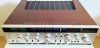
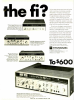
STANDARD SR-4500 SOLID STATE RECEIVER

nicolas25

Active Member
Hello anyone who has info about this vintage receiver? i need also schematics please. there is no voltage on the supply for the lamps. thanks

standard_solid_state_amfm_stereo_receiver_sr_4500.html
 

Attachments

  • solid_state_am_fm_stereo_receiver_2737876.jpg
    solid_state_am_fm_stereo_receiver_2737876.jpg
    18.8 KB · Views: 66
Last edited:
Register to hide this ad
I would:
look all over for a fuse.
Trace the lamp wire to where it gets power.
Make sure someone didn't put the wrong type of lamps in. (I have seen fuses in place of fuse style lamps)

Rob
 
i’ve thoroughly check the fuses, theres a 2 fuse underneath but its not for the lamps. i put 7 new lamps in total incluiding the vu's, all new, 8 volts but still not working
 
Standard Radio, before Marantz, is very hard to find, both physically and any literature.

You might want to include which country version you have and your skill level. For some, tracking down light power is easy, for others, not so much.
 
Is the balance slider in the middle under the large volume knob? In the advert it's far right...... maybe that's why we don't see too many of them?
Just to dismiss the obvious, have you switched the selector to radio?
 
I have one and did a revision. Sadly it's running too hot. Three trimpots per channel, I'd need the schematics or a service manual.

If anyone has them I'd gladly pay for then

Regards,

BB
 
Have a look at the trimmer values, the R value (may) give an indication as to their function.
Good suggestion.

But the board just has a VR designation. To measure the pots I would need to remove the power amplifier from the housing. Which is a lot of work sadly. And because it's all soldered wires it's easy to break them.

I'd rather not go down that road unless absolutely necessary.

I think a schematic would be necessary, best would be a service manual. Otherwise it will be like pissing in the dark.

Kind regards,

Bert
 
The trimmer should have numbers marking their value.
Something like 501, 102, 502, 103.....


As long as you shoot away from your feet.
You are correct, usually the trimpots will have some number for the ohms value. But these trimpots do not, they are not the regular scrappy trimmers.

Measuring them in circuit gives me wonky readings. I'd say best not play with them without a service manual.

Dann shame, it's a really good machine and sounds nice.

Kind regards,

Bert
 
Sadly it's running too hot. Three trimpots per channel
One trimmer is protection. Probably a 500 ohm. Likely followed by a diode.
One trimmer is bias , likely a 1K or such.
One trimmer is center voltage, likely a 10K/20K or such.

The bias and center voltage is simple and in fact you check the settings with a DMM - no need to adjust trimmer (unless there is a misalignment.)

Hope this helps
 
Back
Top Bottom