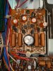
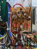
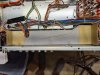
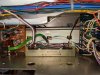
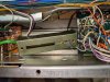
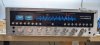
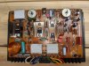
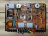
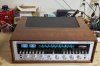
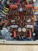
Here is a picture of the P700 circuit board after I did the restoration.
C701 was replaced with a 1.0uf Panasonic cap from the kit. C703 was replaced with a 33uf audio grade electrolytic from the kit. C706 and C707 were replaced with 10uf 50V caps from the kit. I also replaced C702, C710 and C713 with 100pf Wima caps as they were called out in other threads. I replaced the 0.1 Film caps C708, C709, C714 and C721 as folks on Audiokarma advise that the grey films can be problem-prone.
Diodes H718, H719, H720 and H721 were replaced with 1N4148 glass diodes from the kit. The two Zener diodes H716 and H717 were replaced with two 20V 2W Zener diodes from the kit.
1.2K 2W Resistors R719 and R720 were replace with 1 .2K 3W resistors from the kit.
Transistors H701, H702, H703, H711 and H712 were all replaced with KSA992 transistors from the kit. H701/H702 are the differential pair which I matched and coupled together with a dab of heat sink compound between then, using heat shrink tubing to keep them in place.
H704 was replaced with a KSA1013 from the kit. H705,H710 and H713 were replaced with KSC2383's from the kit. The circuit traces for several of the transistors are very close together so a lot of care and a fine-tipped soldering pencil are a must.
H708 was replaced with a MJE15032G and H709 was replaced with a MJE15033G. These are mounted on heat sinks but no mica insulator is used as the heat sink, other than being connected to the collector, is electrically isolated.
H715 which is under the bracket connecting the aluminum heat sink to the circuit board was replaced with a MJE243G from the kit.
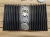
H706 is replaced with a KSA1318 and H707 is replaced with a KSC3503, both from the kit. Both of these new transistors are ECB while the transistors they replace are EBC. The good news is that the new transistors are not metal-backed so you do not need the mica insulators. The bad news is that they are thicker than the ones they are replacing so the mounting hardware screw is too short to secure the dual heat sink to the circuit board. I went to the hardware store and bought a screw that was 1/4 in longer than the factory screw. The thread pitch was different so I bought nuts and lock washers to go with the new screws and mounted the two new transistors on the heat sink with the new screws and the first nut after bending the leads to match the old ones. I bent the center lead a little bit closer to the transistor body to facilitate tucking it over to the "C" hole on the board around the third lead which, in turn, is crossed over to the "B" hole. This must be done for both new transistors and yes, it is a PIA for sure but I found by pre-mounting the two new transistors and bending the center lead a little closer to the transistor it was manageable. Use a piece of clear insulating tubing on the center lead trimmed to fit to prevent the crossed leads from shorting out. The tubing is supplied with the kit. Don't forget to get the heat sink orientated the right way as it goes in either way so the proper replacement transistor is installed in the proper position. You do not want to have to undo things and then do it all again.........What could be easier!!!!
To add to the fun, while you have the dual heat sink out be sure and replace H714 that is under it with a MJE243G supplied with the kit.
The kit also contains replacement fly back diodes which I will install after testing the board in the 2325.
I de-oxed the two trimmer pots and then installed the board back in the 2325 after closely reviewing all the components I installed to be sure the polarities were correct.