

You are using an out of date browser. It may not display this or other websites correctly.
You should upgrade or use an alternative browser.
You should upgrade or use an alternative browser.
Starting my first 2325 Restoration and Looking for Guidance
- Thread starter richiem46
- Start date
-
- Tags
- 2325 first marantz restoration


An update to my 2325 restoration thread. The unit began to have static on the left channel on power-up briefly after about 2 months. The static became of longer duration over time so I received back the 2325 and took a look. I had cleaned the wire-wound DC balance pot R713 as it was the original source of the "scratchy" static on that channel. It worked well for a week on my bench so I thought all was well. I now replaced R713 and R740 the Bias pot with 1K Bourns 20 turn trimmers.
The R713 was slightly more involved in that a "hole" in the board that appeared there for the center (rotor) lead was not correct in that it did not follow the schematic. The rotor in the original pots is tied to the case of the pot so rather that connecting the rotor lead through the hole in the board I ran a short jumper to the left grounding lug on the board to the rotor terminal on the Bourns trimmer. For the Bias pot R740 the hole in the board is correct and I attached the rotor lead of the Bourns trimmer through that hole. I am attaching an annotated picture of the P700 board here for reference. The Bourns pots ship with the rotor centered and I left them in that position when I installed them. I immediately set the bias per the manual and then let the amp warm up thoroughly. The bias and idle current dialed right in and were stable. There was no "touchiness" to the settings, they dialed in smoothly. The settings are completely stable after several days of use. I was reluctant to replace the pots originally as they are wire-wound but they do not dissipate very much power so I replaced them. Lesson learned, good or bad they get replaced going forward.
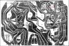
The R713 was slightly more involved in that a "hole" in the board that appeared there for the center (rotor) lead was not correct in that it did not follow the schematic. The rotor in the original pots is tied to the case of the pot so rather that connecting the rotor lead through the hole in the board I ran a short jumper to the left grounding lug on the board to the rotor terminal on the Bourns trimmer. For the Bias pot R740 the hole in the board is correct and I attached the rotor lead of the Bourns trimmer through that hole. I am attaching an annotated picture of the P700 board here for reference. The Bourns pots ship with the rotor centered and I left them in that position when I installed them. I immediately set the bias per the manual and then let the amp warm up thoroughly. The bias and idle current dialed right in and were stable. There was no "touchiness" to the settings, they dialed in smoothly. The settings are completely stable after several days of use. I was reluctant to replace the pots originally as they are wire-wound but they do not dissipate very much power so I replaced them. Lesson learned, good or bad they get replaced going forward.
Last edited:
A picture of one of the P700 boards with the Bourns trimmers installed.

Here are the four pots I removed from the 2325 P700 boards. The one on the left is the bad unit. They look very clean inside but as I learned, appearances can be deceiving.
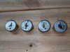
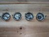
Here are the four pots I removed from the 2325 P700 boards. The one on the left is the bad unit. They look very clean inside but as I learned, appearances can be deceiving.
A bit of a side note, I have been reading about folks installing jumpers between the Pre-out Main-in jacks to improve sound quality and to circumvent possible issues with the internal switches on the RCA jacks. I installed a pair of 3 Ft. jumper cables between the jacks and I thought the sound was "cleaner" with the patch cables installed.
I did some research and this is quite a lively topic. One side is certain just the "right" metal jumper sounds superior while others state that any short quality parch cord works equally well. (I am kind of in this camp personally).
I did obtain some #8 solid copper grounding wire to attempt to make my own jumpers but my metallurgical skills need some work as the pictures below show. The #8 wire is the perfect diameter but bending it to shape was more challenging than I anticipated. I did get one to fit properly and to me it sounded the same as the patch cable. I also noticed that after installing and removing the patch cables several times the amp sounded the same with or without the cables. Maybe the repeated insertion/removal cycles cleaned up the internal connections. Or maybe I was hearing the power of suggestion.............
I will clean the internal switches on the RCA jacks.............

I did some research and this is quite a lively topic. One side is certain just the "right" metal jumper sounds superior while others state that any short quality parch cord works equally well. (I am kind of in this camp personally).
I did obtain some #8 solid copper grounding wire to attempt to make my own jumpers but my metallurgical skills need some work as the pictures below show. The #8 wire is the perfect diameter but bending it to shape was more challenging than I anticipated. I did get one to fit properly and to me it sounded the same as the patch cable. I also noticed that after installing and removing the patch cables several times the amp sounded the same with or without the cables. Maybe the repeated insertion/removal cycles cleaned up the internal connections. Or maybe I was hearing the power of suggestion.............
I will clean the internal switches on the RCA jacks.............

Just a suggestion for making the jumpers. Don't cut the wire first. Take a longer piece of wire, then bend it into a U-shape around a wooden dowel used as a form. Then, cut the ends to length and file smooth. That way you are not trying to grab a small piece of wire while you bend it. Using a dowel or other cylindrical object as a form will ensure a smooth semi-circle arc and repeatable size. 
Also, I'm not sure that you want to use copper since it will oxidize. You may want gold or silver plated wire.
Also, I'm not sure that you want to use copper since it will oxidize. You may want gold or silver plated wire.
Last edited:
I was leaning towards short shielded jumpers as it makes the most sense to me although since cleaning the RCA jacks I really do not hear any difference with or without the jumpers. To be cautious I will use the short jumpers as they are kind of a "fail-safe" especially if I plan to ship the unit. With a weight of 65 Lbs. with the wood case they tend to get slammed around a lot.
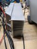
I decided to perform some additional testing on the 2325 to make sure it is performing up to specifications and to get further experience with the whole process. I used two 8 ohm 100W non-inductive resistors to align the power amps in the Rotel 1412 I restored. They worked but got VERY hot during the testing. I was operating them right at (and a bit beyond) their ratings so I decided to attach them to a heat sink. I put thermal compound on them before fastening them down with sheet metal screws. Here are a few pictures of the end product:

I connected the 8 ohm dummy load to the 2325 main speaker outputs. I drove the 2325 through the AUX inputs with a signal generator at 1Khz. I attached a Fluke Digital meter to the right channel and my scope to both the left and right channels to monitor for clipping during the test. I applied the signal and started to turn up the volume watching the scope and Digital Meter. The voltage wasn't rising very significantly when all of a sudden the Scope kind of went a bit wonky on the right channel and the Meter jumped all over the place. I immediately turned off the signal, then applied it again with the same result.
I suspected some sort of oscillation but could not really be sure. I then noticed the Right channel heat sink was extremely warm, the transistors themselves too hot to touch. Powered down immediately and scratched my head a bit. I then remembered reading how the scope negative leads were tied together in the scope to earth ground via the 3 prong power plug. This was tying together the two negative speaker terminals on the 2325 and in turn tying them to earth ground. I am not sure of the technical details of what was going on but I them tied the two negative scope connectors to the speaker negative terminals through a .068 UF cap to isolate the negative connections (scope was set to A/C coupling all along).
After waiting a few minutes for things to cool down I powered the 2325 back up and advanced the volume. The scope and meter readings behaved normally now, advancing gradually as I increased the volume on the 2325. I was able to drive it up to rated output with this configuration ultimately. I will detail some of this process in subsequent posts. I was just relieved that I did not damage the 2325 when I connected it initially.
I suspected some sort of oscillation but could not really be sure. I then noticed the Right channel heat sink was extremely warm, the transistors themselves too hot to touch. Powered down immediately and scratched my head a bit. I then remembered reading how the scope negative leads were tied together in the scope to earth ground via the 3 prong power plug. This was tying together the two negative speaker terminals on the 2325 and in turn tying them to earth ground. I am not sure of the technical details of what was going on but I them tied the two negative scope connectors to the speaker negative terminals through a .068 UF cap to isolate the negative connections (scope was set to A/C coupling all along).
After waiting a few minutes for things to cool down I powered the 2325 back up and advanced the volume. The scope and meter readings behaved normally now, advancing gradually as I increased the volume on the 2325. I was able to drive it up to rated output with this configuration ultimately. I will detail some of this process in subsequent posts. I was just relieved that I did not damage the 2325 when I connected it initially.
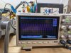
With the correct test connections I started to test the left channel to see how much power was being dissipated when I drove it to clipping with a 1Khz. Sine Wave. The output on the scope started to clip at about 36.9V RMS. The reading on the Fluke meter correlated the scope reading. Ohm's Law I=E/R 36.9/8 Ohms =4.6125 Amps 4.6125 X 36.9 V = 170 W RMS if my math is correct. Not bad for an amp rated at 125W per channel.
The left channel transistors and heat sink got quite warm during this test but not nearly as warm as the right one did during the instability I experienced earlier. The dummy load got quite warm but not too hot in that I was only driving one channel.
Here is a picture of the scope output during this test:
The left channel transistors and heat sink got quite warm during this test but not nearly as warm as the right one did during the instability I experienced earlier. The dummy load got quite warm but not too hot in that I was only driving one channel.
Here is a picture of the scope output during this test:
Matt Giarra
Member
Just curious, how much did you pay for the 2325? I’ve seen some massively expensive ones.
I performed the same test on the right channel and achieved the same results, about 170W RMS output at 1Khz.
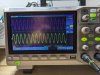
I then performed a test driving both channels at 1Khz until I observed clipping on both channels. The picture below shows output on both channels. at 33V RMS which translates to 136W RMS per channel which again is well within specifications for a receiver rated at 125 W per channel.
I increased the volume a bit more and at about 150 Watts per channel there was noticeable clipping at 1Khz.
To test the protection circuits I increased the volume until there was significant clipping with both channels driven. I wanted to make sure that the 2325 could withstand some abuse and not fail.
At about 175 WPC the 2325 went into protection. I reduced the volume and after 5-10 seconds it came out of protection and functioned normally. I repeated this action two more times and then figured that I should not tempt fate any further.
The output heat sinks were quite warm at this point but again not alarmingly so.
The speaker dummy load whoever, was too hot to to touch more then briefly. I definitely was stressing it's capabilities during this test.
I repeated the dual channel test at several frequencies up to 20Khz. At the higher frequencies the amplifier did not exceed the 125 WPC rating as much as it did at 1Khz but it within specs at 125WPC.
Definitely a very capable receiver.
I then performed a test driving both channels at 1Khz until I observed clipping on both channels. The picture below shows output on both channels. at 33V RMS which translates to 136W RMS per channel which again is well within specifications for a receiver rated at 125 W per channel.
I increased the volume a bit more and at about 150 Watts per channel there was noticeable clipping at 1Khz.
To test the protection circuits I increased the volume until there was significant clipping with both channels driven. I wanted to make sure that the 2325 could withstand some abuse and not fail.
At about 175 WPC the 2325 went into protection. I reduced the volume and after 5-10 seconds it came out of protection and functioned normally. I repeated this action two more times and then figured that I should not tempt fate any further.
The output heat sinks were quite warm at this point but again not alarmingly so.
The speaker dummy load whoever, was too hot to to touch more then briefly. I definitely was stressing it's capabilities during this test.
I repeated the dual channel test at several frequencies up to 20Khz. At the higher frequencies the amplifier did not exceed the 125 WPC rating as much as it did at 1Khz but it within specs at 125WPC.
Definitely a very capable receiver.