

You are using an out of date browser. It may not display this or other websites correctly.
You should upgrade or use an alternative browser.
You should upgrade or use an alternative browser.
sunday morning organ salvage comin down...

And the Jensen field coil speakers are not a lot different. Magnevox and Jensen were in cahoots for a while,but i don't remember all of the history on the topic.
FYI - Danish-American inventor Peter Jensen founded the company later named Magnavox (1911), invented the moving coil speaker (1915) - earliest ones used a horn - resigned Magnavox to start Jensen Radio (1925). Cahoots indeed!

trobbins
Super Member
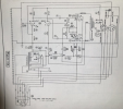
Thanks for the schem of the power/amp. Interesting filter configuration for B+
Did you get a schem of a tone panel, or other circuitry?
I just finished a decade long restoration of an electronic organ - labour of love. Luckily its 63 Mullard 12AX7 were all pretty much 'norminal'
Did you get a schem of a tone panel, or other circuitry?
I just finished a decade long restoration of an electronic organ - labour of love. Luckily its 63 Mullard 12AX7 were all pretty much 'norminal'

i have the entire manual for model 40-45Thanks for the schem of the power/amp. Interesting filter configuration for B+
Did you get a schem of a tone panel, or other circuitry?
my friend, im just beginning to re-familiarize myself with the circuit basics, and ive been studying the manual. i havent soldered since 2009 or earlier. next is pickin up a soldering station.Thanks for the schem of the power/amp. Interesting filter configuration for B+
im curiou anout that B+ comfiguration—whats the scoop?
oh wow. i can barely imagine the work. my word. it musta been like engine overhaul or something.I just finished a decade long restoration of an electronic organ - labour of love. Luckily its 63 Mullard 12AX7 were all pretty much 'norminal'
im assuming the restoration included the cabinet as well. what kind of shañe was itnin when i got it?
do you have any of the restoration documented here on AK or elsewhere?
my goal is a lot simpler—convert 2 of these amps to standalone home stereo use.
trobbins
Super Member
The 8H choke is located in the CT line to ground, rather than the more typical B+ feed between the two 4uF filter caps.
The Selmer Concert organ I have restored came in complete almost original condition. It is still the only complete unit I know of in existence, and only had offers from someone who just wanted the valves removed and posted off, with the remainder to be ditched. It doesn't hold a spot in the annals of history, like for example the M3, but has shown up a wealth of technical and cultural history, including being the first organ used by a prominent concert organist.
https://dalmura.com.au/projects/Selmer Organ.html
The Selmer Concert organ I have restored came in complete almost original condition. It is still the only complete unit I know of in existence, and only had offers from someone who just wanted the valves removed and posted off, with the remainder to be ditched. It doesn't hold a spot in the annals of history, like for example the M3, but has shown up a wealth of technical and cultural history, including being the first organ used by a prominent concert organist.
https://dalmura.com.au/projects/Selmer Organ.html

knockbill
Lunatic Member
Caps and resistors are done by now,,, but I would save those turret boards!!!!!ive finished the complete disassembly of one organ and the removal of audio components of another, and i have some questions i reckon the community may help teach and inform me.
1. the caps and resistors of use to anyone? if so, do i try to de-solder or just clip em out?
ah! will do. thanks for the good advice.Caps and resistors are done by now,,, but I would save those turret boards!!!!!

unga-unga
Active Member
Hmm the caps conservation conversation IS an ENTIRE discussion on its own, and there are defensible aspects to both "sides." I don't think there's a simple black & white truth about the functionality of a really old cap. Wax caps like those blue/green ones here are maybe the most suspicious as a category... however, I think the accurate statement is, "too often they are bad, and too difficult are they to test, to justify much other than replacing them all first, and if you wanna save them, you can evaluate them when there is endless time or no obligation to a customer."
I think it's probably good to create the habit right now of saving any and all "oil" caps though. Those metal ones are, maybe, or maybe they're electrolytic I'll go look again...
Anyways, I just think a junk drawer is a good place for them as opposed to the garbage... but I hoarde so.
I think it's probably good to create the habit right now of saving any and all "oil" caps though. Those metal ones are, maybe, or maybe they're electrolytic I'll go look again...
Anyways, I just think a junk drawer is a good place for them as opposed to the garbage... but I hoarde so.
understood. its the trash for these.Hmm the caps conservation conversation IS an ENTIRE discussion on its own, and there are defensible aspects to both "sides." I don't think there's a simple black & white truth about the functionality of a really old cap. Wax caps like those blue/green ones here are maybe the most suspicious as a category... however, I think the accurate statement is, "too often they are bad, and too difficult are they to test, to justify much other than replacing them all first, and if you wanna save them, you can evaluate them when there is endless time or no obligation to a customer."
cool.I think it's probably good to create the habit right now of saving any and all "oil" caps though. Those metal ones are, maybe, or maybe they're electrolytic I'll go look again...
i can relateAnyways, I just think a junk drawer is a good place for them as opposed to the garbage... but I hoarde so.

trainbuftony
Electron Herder
I put the caps from my organ part outs on ebay. People buy them and I spend the money on good caps, tube sockets, transformers or hamburgers, whatever I need at the time. Not worth the time to test them just fill a zip lock bag and collect your reward.

A bit late on this 2c worth, but my limited experience has shown that them micamold tropicaps tend to be on the crappy side of vintage caps electrically speaking. Some other brands last a bit longer. I concur with being bin filler, or make industrial jewelry or art with those, along with the colorful carbone resistors.ive finished the complete disassembly of one organ and the removal of audio components of another, and i have some questions i reckon the community may help teach and inform me.
1. the caps and resistors of use to anyone? if so, do i try to de-solder or just clip em out?
View attachment 2845478 View attachment 2845479
View attachment 2845480
2. theres one of these on at the end of every bosrd/section lf the tone generator. the darker beown appears to be wax. what is it? anyone have an idea?
View attachment 2845481
3. this lil transcormer-lookin component look familiar?
View attachment 2845485
gotcha. thank u very much my friendA bit late on this 2c worth, but my limited experience has shown that them micamold tropicaps tend to be on the crappy side of vintage caps electrically speaking. Some other brands last a bit longer. I concur with being bin filler, or make industrial jewelry or art with those, along with the colorful carbone resistors.
@gadget73, @Dswankey, @nerdorama, @Tom Bavis, @trobbins and the rest of you helpful folks,
i have the schematic and have studied it; i have my 600V auto-ranging multimeter and avariac. got plenty of tubes. no soldering gear, yet, but i havent soldered since maybe 2007, 2009. cant make up my mind about buyin the hakko or a Yihua 948 budget open box full set for sale locally.
the top of the chassis is dirty,
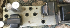 but a good look at the underside i dont see burnt resistors or leaky caps anywhere.
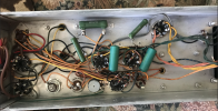 what is my first step to take with one of these amp?
do i plug the speaker back in to the amp
the rig up a source
then clip all the cables on the long cable assembly and add a plug to the 115VAC lines, plug her in to the variac and bring her up real slow?
i have the schematic and have studied it; i have my 600V auto-ranging multimeter and avariac. got plenty of tubes. no soldering gear, yet, but i havent soldered since maybe 2007, 2009. cant make up my mind about buyin the hakko or a Yihua 948 budget open box full set for sale locally.
the top of the chassis is dirty,
but a good look at the underside i dont see burnt resistors or leaky caps anywhere.what is my first step to take with one of these amp?do i plug the speaker back in to the amp
the rig up a source
then clip all the cables on the long cable assembly and add a plug to the 115VAC lines, plug her in to the variac and bring her up real slow?

Thats the right answer but the right now answer to see if there is any life is to knock together a solid state rectifier with say 100 ohms or so of current limiter resistor between the diodes and the output to the first cap. Bring it up slow and monitor for voltage drop across the resistors between each cap section. With no tubes, good caps will give no voltage drop. Can also check the coupling caps for leakage by measuring voltage across the grid to ground resistors. No cap leakage means no voltage. Watch you don't exceed any cap ratings with no other load on the supply.
Total crapshoot if this works. I did it earlier in the week with something from 1940 snd 3/4 sections came up ok, then 30 minutes later they started getting warm.
Total crapshoot if this works. I did it earlier in the week with something from 1940 snd 3/4 sections came up ok, then 30 minutes later they started getting warm.
ok. how do i do that? im ready to give it a shot.Thats the right answer but the right now answer to see if there is any life is to knock together a solid state rectifier with say 100 ohms or so of current limiter resistor between the diodes and the output to the first cap. Bring it up slow and monitor for voltage drop across the resistors between each cap section. With no tubes, good caps will give no voltage drop. Can also check the coupling caps for leakage by measuring voltage across the grid to ground resistors. No cap leakage means no voltage. Watch you don't exceed any cap ratings with no other load on the supply.
Total crapshoot if this works. I did it earlier in the week with something from 1940 snd 3/4 sections came up ok, then 30 minutes later they started getting warm.

You can do the variac slow start but need to monitor current somehow. Put a 10k or 20k power resistor between the rectifier and first cap so you can monitor the voltage drop and protect things. I use a Kil-a-watt monitor to watch the line current. If the power up with the big resistor goes ok, let it burn for a while before bypassing or removing the resistor.
yesGot a junk octal tube you can rob a base from,
nosome 1n4007 rectifiers and a resistor?
could i monitor with gator clips and an ammeter/multimeter? my multimeter has a 10A settingYou can do the variac slow start but need to monitor current somehow. Put a 10k or 20k power resistor between the rectifier and first cap so you can monitor the voltage drop and protect things. I use a Kil-a-watt monitor to watch the line current. If the power up with the big resistor goes ok, let it burn for a while before bypassing or removing the resistor.