• The move to the new server is done. There are some software and database maintenance updates in process. This has us passing the hat around to help out. We appreciate any donations. Seriously, even a dollar helps. The payment page may be found here - https://www.audiokarma.org/support.html

Super Chorus inspired project.

Another analogy regarding non-optimum use of an item or system is a bass reflex enclosure. According to the Loudspeaker Design Cookbook (and many other similar sources for speaker design) you do not want any ripple in your calculated box alignment. Trying to get a woofer to perfectly match a mathematical alignment is not easy. In a less than perfect match, a bass reflex enclosure may have 3~4dB of ripple and you look at the simulated graph and go "ugh", but in reality, that alignment could sound great and in a lot of cases it does. My Super Heresy using the Celestion TF1225 woofer simulates OK with some ripple, but you would never know it listening to it. The sound far outshines any simulation results.
 
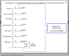
so, connect to both the 3and 4 taps for 15dB?

Yep, it's all about the ratio between the input turns and the output turns.

The turns between taps 1 - 0 equal 25% of the 5 - 0 turns, therefore the voltage across 1 - 0 is 25% of the voltage across 5 - 0, or -12db. It so happens that the turns between 4 - 3 equal 18% of the 5 - 0 turns, therefore the voltage across 4 - 3 is 18% of the voltage across 5 - 0, or -14.9db.

05818C3D-D041-4948-A389-D546E9BFBA4B.jpeg
 
as far as the 2nd paragraph goes, I recognize the words you’ve typed as being English, but I’m not entirely certain about what you’ve written. Can you explain that to someone who built their first speaker 6 months ago? Pictures help. o_O

Here are plots of two crossovers using T2A's and the -12db output taps. The red is with a "swamping" resistor, the green without. I adjusted the capacitor values to reflect the different loads to better illustrate my point.

In both cases, the autoformer acts like the inductor portion of a second order high pass to the squawker. The inductance between taps 5 - 0 on a T2A is 45.6mh. The inductance between taps 1 - 0 on the T2A is 2.8mh. With the resistor, the entire 45.6mh inductance results in a gentler slope compared to the 2.8mh inductance without the resistor.

T2A vs T2ASwamper.png
 
All this is true. The D2200Ph does have an entirely different impedance sweep on the 18x10 horn vs the K55V on the K400. However, despite my non-optimum low crossover of 400Hz of the 2200Ph & 18 x 10, a system (entire loudspeaker) impedance sweep with a universal type crossover (with swamping resistor) shows a fairly flat impedance curve. Since this is on the amp side of the circuit, a flat impedance curve will not relate to any sonic activity of the driver / horn combo.

But, a sweep of REW from an acoustic point of view shows no detrimental effects in the midrange frequency response from 400Hz to 6kHz. This range of frequencies is extremely flat nearfield.

I'm still contemplating/investigating the issue of the D2200Ph resonance being right around the crossover point, but have not come up with any thoughts on it yet.
Well, effectively, that 33 uF cap the driver comes with is cheap, but also the higher impedance creates a lower crossover point than the "textbook" 600 Hz. for that cap. I have yet to measure them in ZXYC horn. Maybe next week.
 
The best way to tackle the driver resonance issue is with a series notch filter. That still leaves the question of "is the 2200Ph resonance too low to operate correctly in the desired frequency range?", which in my case is 400Hz ~ 6kHz. I've been cognizant of the issue, but since Dean brought it up, I figured I'd offer a solution if anyone was interested or they thought using the 2200Ph driver below it's natural resonance would be an issue.

Driver Impedance Curve Example.png

Driver Series Notch Filter_1.png

Driver Series Notch Filter_2.png

Using the shortcut method with REW should yield fairly quick results.
 
I put on Beck's Sea Change when I got home from my Thursday night MTB ride/race tonight with fresh ears and lessened expectations. They're incredibly revealing, more goosebumps and hair-raising. when I built both the original; H-700 Super Heresy's and later, the super heresy clones, both, in turn, were the best speakers I'd ever heard/owned. The subsequent mods that I did to them, first the K610 horns and PRV Audio D270-PH drivers and later, the bass bins, with Dayton Audio !5" passive woofers yielded significant improvements in SQ, but the K510 clones with the PRV Audio 510 drivers are an order of magnitude better, even in their janky, crude state. if my Frankenstein assemblage sounds this good, I can't wait to hear what a properly simulated and intentionally constructed version will sound like.
 
Not with that schematic. You need to float the common connection for the squawker.

Hey Dean...I'm confused (again). In my -15db schematic did I not disconnect the + side of the K55V from common? Isn't this what you mean by floating?

Mike
 
Hey Dean...I'm confused (again). In my -15db schematic did I not disconnect the + side of the K55V from common? Isn't this what you mean by floating?

Mike
I believe Dean is saying you need to disconnect the ground from the "0" terminal and let it (0) float or something to that effect, but you need two connections somewhere.
 
Right. On the network side of the barrier strip, there should be no squawker negative. If negative is connected all you will get is -3 -6 -9 and -12.

In the latest design, using an autoformer with three input terminals, you do connect it - and so you get up to 15 dB of attenuation in one dB increments.
 
To be clear, on the barrier strip, the common ground wire would bypass the squawker section altogether?

Correct. I should have made that clearer in my schematic but didn't know how. With both posts of the squawker output not connected to common, you will need to connect each to the autoformer.
 
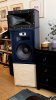
The caps to drop the crossover frequency have been delayed until Monday, so I made a pair of temporary enclosures after work today for better WAF; my gf had made veiled remarks about naked horns in the past. As an added bonus, this will prep her for the new speakers, which will be about an inch taller, 3-1/2” wider and a little deeper. I also put the mumps from the k604s in; it does sound better.

A7CD8874-7DD9-4559-9E80-E689AA5C7003.jpeg
 
Last edited:
Can’t remember what you told me about what the swapping resistor does to the inductance. Up or down?
 
Can’t remember what you told me about what the swapping resistor does to the inductance. Up or down?

For reasons I can't figure out, the swamping resistor seems to maintain the inductance of the entire autoformer, regardless of the output taps used. So, for a T2A, the parallel inductance is always 45.6mh. For a 3636 or 3619, it will always be almost twice that.
 
In lieu of changing the networks due to shipping delays, I disconnected the sMAHLs and hooked up the the l-MAHLs, so it’s more or less at its ultimate configuration, less about 76 liters of displacement. Le LMAHLs are a definite improvement over the sMAHLs, but not as dramatic an improvement over K77s. I’ve decided to make a few compromises in order to reduce unwanted resonance, so it likely won’t dig as deep as I‘d wanted, but it should sound pretty great just the same.

334111A1-8E78-479A-B329-EB70A8F47281.jpeg
 
Back
Top Bottom