

You are using an out of date browser. It may not display this or other websites correctly.
You should upgrade or use an alternative browser.
You should upgrade or use an alternative browser.

merlynski
Curmudgeon Electronicist
The left channel looks about nominal, C37 and C39, but the right channel looks high.
Have you rebuilt this board? Transistors sb 512-KSC1845FTA.
On mine I replaced all the signal path caps, 10µF and under with film, and the 100µF electrolytics with 647-UPW1V101MPD, 100µF 35v.
Have you rebuilt this board? Transistors sb 512-KSC1845FTA.
On mine I replaced all the signal path caps, 10µF and under with film, and the 100µF electrolytics with 647-UPW1V101MPD, 100µF 35v.

dustmaker
Active Member
Yes - I did rebuild it. All trans and all e-caps.The left channel looks about nominal, C37 and C39, but the right channel looks high.
Have you rebuilt this board? Transistors sb 512-KSC1845FTA.
On mine I replaced all the signal path caps, 10µF and under with film, and the 100µF electrolytics with 647-UPW1V101MPD, 100µF 35v.
I will check orientation of trans and caps
dustmaker
Active Member
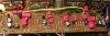
OK - not sure how I did it, but I had two transistors in at wrong orientation and one e-cap backwards.
It does work now.
I used 647-UKL1H2R2KDDANATD for all the small e-caps. I got that part number from post https://audiokarma.org/forums/index...-rebuild-parts-list-completed-project.925512/. I meant to use your parts list but this is the one I clicked on and selected.
I also just upgraded the 2200mF e-cap on the -104 (I just recently purchased one)
I still have a few resistors to update on the -103.
I never did replaced the matched transistors on the equalizer board (maybe down the road when I do the circuit and scope to do matching)
Once I update the -103 resistors, I guess I’m done? I’ll check/adjust VR1/2 AND VR3/4 after a thorough warm up.
Anything else I should do while I’m in here?
I’m still trying to get a signal generator to do the distortion testing, I may have to buy one. Any recommendations in this area?
It does work now.
I used 647-UKL1H2R2KDDANATD for all the small e-caps. I got that part number from post https://audiokarma.org/forums/index...-rebuild-parts-list-completed-project.925512/. I meant to use your parts list but this is the one I clicked on and selected.
I also just upgraded the 2200mF e-cap on the -104 (I just recently purchased one)
I still have a few resistors to update on the -103.
I never did replaced the matched transistors on the equalizer board (maybe down the road when I do the circuit and scope to do matching)
Once I update the -103 resistors, I guess I’m done? I’ll check/adjust VR1/2 AND VR3/4 after a thorough warm up.
Anything else I should do while I’m in here?
I’m still trying to get a signal generator to do the distortion testing, I may have to buy one. Any recommendations in this area?
dustmaker
Active Member
I hope you had a picture and didn’t re-access this board to photograph. That would be a lot of work just for a picture. In hindsight, I wish I took pics of all my boards as each pcb was completed.2SC1312 (from Tone pcb) is BCE
KSC1845 (replacement) is ECB
The replacements face the other direction than the originals.
My Tone Amp after rebuild:
View attachment 2010047
Not one of my better pictures.
All of my transistors on this board have a -5.4 vdc base, which makes sense since I am running a bit high on negative voltage throughout the unit
merlynski
Curmudgeon Electronicist
I take many before and after pictures (from AK long time re-furbisher recommendations), and every time I look back I wish I had taken more. I need a better camera for close-up. That part of my amp is all re-assembled and buttoned up. All I have left is the phono equalizer. Vbe Matching circuit: DIY Transistor Matching Circuit I have noticed that the AK matching emphasis has changed from matching gain (hFE) to matching Vbe.
I had seen the symptoms you described on the tone board before, and is was mis-oriented transistors. Since it was a 'working unit' before you started rebuilding it, my troubleshooting thinking figured it was likely a change you made.
For a low distortion oscillator I would probably build one, I have seen many circuits recommended that don't look too difficult.
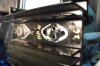
As for anything else to do, I would put new thermal compound (and maybe mica) on the output transistors. I also flattened the raised mounting surface of the heatsink for the output transistors a bit with a fine file to get better heat transfer.

I had seen the symptoms you described on the tone board before, and is was mis-oriented transistors. Since it was a 'working unit' before you started rebuilding it, my troubleshooting thinking figured it was likely a change you made.
For a low distortion oscillator I would probably build one, I have seen many circuits recommended that don't look too difficult.
As for anything else to do, I would put new thermal compound (and maybe mica) on the output transistors. I also flattened the raised mounting surface of the heatsink for the output transistors a bit with a fine file to get better heat transfer.
dustmaker
Active Member
Very impressive OCD on filing down heat sinkI take many before and after pictures (from AK long time re-furbisher recommendations), and every time I look back I wish I had taken more. I need a better camera for close-up. That part of my amp is all re-assembled and buttoned up. All I have left is the phono equalizer. Vbe Matching circuit: DIY Transistor Matching Circuit I have noticed that the AK matching emphasis has changed from matching gain (hFE) to matching Vbe.
I had seen the symptoms you described on the tone board before, and is was mis-oriented transistors. Since it was a 'working unit' before you started rebuilding it, my troubleshooting thinking figured it was likely a change you made.
For a low distortion oscillator I would probably build one, I have seen many circuits recommended that don't look too difficult.
As for anything else to do, I would put new thermal compound (and maybe mica) on the output transistors. I also flattened the raised mounting surface of the heatsink for the output transistors a bit with a fine file to get better heat transfer.
View attachment 2010269
View attachment 2010271
looking at the transistor matching circuit, this one is very simple and straight forward...but I still have a question. when you have a battery circuit as depicted, where is the ground? Would I be connecting a wire from an electrical outlet ground to this circuit or is there a better way to secure a ground connection?
merlynski
Curmudgeon Electronicist
It does not literally need to be grounded. The ground is the common point of the two supplies (or batteries). The +12v supply has its - side grounded, the -12v supply has its + side grounded. The diode is there to control collector saturation. Download the pdf from the link above the picture, it explains it very well.

 |
| |
|
I also bought a pair of 0.1% 100k resistors for the transistor tester. Now I just have to build it to match for the phono equalizer transistors.
Yeah, I thought so too, but I could not resistVery impressive OCD on filing down heat sink
||I also bought a pair of 0.1% 100k resistors for the transistor tester. Now I just have to build it to match for the phono equalizer transistors.
Last edited:
dustmaker
Active Member
Theory question..... do the resistors need to be .1%. if you test several 5% and find a match of two say 98,000 ohm resistors? Wouldn’t that work?It does not literally need to be grounded. The ground is the common point of the two supplies (or batteries). The +12v supply has its - side grounded, the -12v supply has its + side grounded. The diode is there to control collector saturation. Download the pdf from the link above the picture, it explains it very well.
Yeah, I thought so too, but I could not resist
I also bought a pair of 0.1% 100k resistors for the transistor tester. Now I just have to build it to match for the phono equalizer transistors.
merlynski
Curmudgeon Electronicist
No, they don't need to be 0.1%, that wast just my OCD Perfectionism (and a bit of humor), and they were available from Mouser for only $5.00 each.Theory question..... do the resistors need to be .1%. if you test several 5% and find a match of two say 98,000 ohm resistors? Wouldn’t that work?
The exact value is not important, if you match a pair with your meter you will probably be as close as the same meter can read the voltage any way, unless you have a very high accuracy meter. Read the PDF, it tells how to overcome the tolerance difference in the resistors very easily.
dustmaker
Active Member
Another theory question
Instead of testing 20 resistors to find two with identical resistance....what if I take one as the target... and add resistors in parallel and series to the other one to get an exact resistance match. If one electrical path is 5 inches long and the other is 1 inch long but they have the same resistance value, would that work or would I be introducing distortion or some other undesirable signal into the circuit?
Instead of testing 20 resistors to find two with identical resistance....what if I take one as the target... and add resistors in parallel and series to the other one to get an exact resistance match. If one electrical path is 5 inches long and the other is 1 inch long but they have the same resistance value, would that work or would I be introducing distortion or some other undesirable signal into the circuit?
merlynski
Curmudgeon Electronicist
Depends on the frequency of the signal and the propagation delay through the circuit, since light travels just less than a foot in a nanosecond. BUT you would have an unbalanced circuit since the one with more resistors would be heavier. Of course you could paint it white, then it would be lighter. But since it has more surface area it could dissipate more power before it let the magic smoke out, even if it was the same resistance.

 Sorry, I couldn't resist . . .
Or I could just buy you a pair of 0.1% resistors. DC won't care, but that is more work than even my OCD can handle.
Sadly, I have seen pictures here on AK where that has been done to get enough power dissipation out of a bunch of 1/4 watt resistors. One of the Tech types found it when he opened a unit to work on it after somebody else's failure to repair.
Here, read the PDF:
Sorry, I couldn't resist . . .Or I could just buy you a pair of 0.1% resistors. DC won't care, but that is more work than even my OCD can handle.
Sadly, I have seen pictures here on AK where that has been done to get enough power dissipation out of a bunch of 1/4 watt resistors. One of the Tech types found it when he opened a unit to work on it after somebody else's failure to repair.
Here, read the PDF: