• The move to the new server is done. There are some software and database maintenance updates in process. This has us passing the hat around to help out. We appreciate any donations. Seriously, even a dollar helps. The payment page may be found here - https://www.audiokarma.org/support.html

SX-1050 rebuild of working unit

Depends on the frequency of the signal and the propagation delay through the circuit, since light travels just less than a foot in a nanosecond. BUT you would have an unbalanced circuit since the one with more resistors would be heavier. Of course you could paint it white, then it would be lighter. But since it has more surface area it could dissipate more power before it let the magic smoke out, even if it was the same resistance.
View attachment 2010555View attachment 2010563 Sorry, I couldn't resist . . .

Or I could just buy you a pair of 0.1% resistors. DC won't care, but that is more work than even my OCD can handle.
Sadly, I have seen pictures here on AK where that has been done to get enough power dissipation out of a bunch of 1/4 watt resistors. One of the Tech types found it when he opened a unit to work on it after somebody else's failure to repair.
Here, read the PDF:
I like the unbalanced because one would be heavier. You are really digging deep to come up with that one!
 
Ok- I have a problem.

I was updating some resistors on the -103. I replaced R19 and R21 and I turned the unit on while on 100watt DBT and 2 fuses blew instantly. I repeated with exact same result. I looked at the -103 pcb and I don’t see any stray wire or solder bridges, etc. None of the components are leaning into the leads on other components.

testing the -103 with a MM, I get a continuity between pin 1 and Pin 4 (ground). I don’t see anything that would cause this. The only thing I did was manipulate the unit onto its side and it’s top and bottom, so I think I may have pulled a wire that is causing a short, I checked everything I can with no luck.

What’s the best way to run this down?
 
Pin 1 on the -103 goes to pin 8 on the -104, pin 9 on the 104 is ground. Look and see if the pins are bent or shorted near there.
 
Found it. Your comment helped me find it. One of the last things I did the other day was replace the 2200mF e-cap on the -104. I NEVER TRIMMED THE LEADS. In the course of my final adjustments earlier, I must have pushed on the -104 to properly seat it and the 1-1/2 “ long bent leads then shorted to the chassis. I clipped them, reseated the -104, tested on 60watt DBT, then 100watt DBT, then live.

i’m back in business. Feeling rather sheepish, but happy none-the-less.
 
Last edited:
I haven’t yet acquired a low distortion signal generator, but I do have a cheapy signal generator. Here are the specs
Specification :
The main output waveform : sine wave and square-wave, triangle wave, sawtooth wave.
Maximum output amplitude : ± 10Vpp (no-load)
Output impedance : 50Ω±10%
Dc bias : ± 10V (no-load)
Display : LCD1602
Resolution : 1 Hz
Power supply : DC 3. 5-10V
Output frequency range :
Sine wave : 1Hz-500KHz
Square-wave : 1 Hz - 20kHz (the valid range)
Triangle wave : 1 Hz - 20KHz (the valid range)
Sawtooth wave : 1 Hz - 20kHz (the valid range)

Would this be sufficient to do a distortion testing?
 
Measure the distortion of the sine wave output directly from the signal generator. What you measure at output from the amp can not be better than the input.
The other signals are combinations of other harmonics, square is made up of a sum all the odd harmonics, triangle wave is the sum of all the even harmonics. Sawtooth wave contains all the integer harmonics.

This site has great info and is a real down-to-earth source for DIY projects, here is a link to a low distortion oscillator: https://sound-au.com/project174.htm
 
Last edited:
Measure the distortion of the sine wave output directly from the signal generator. What you measure at output from the amp can not be better than the input.
The other signals are combinations of other harmonics, square is made up of a sum all the odd harmonics, triangle wave is the sum of all the even harmonics. Sawtooth wave contains all the integer harmonics.

This site has great info and is a real down-to-earth source for DIY projects, here is a link to a low distortion oscillator: https://sound-au.com/project174.htm
I’m looking at the link for a DIY low distortion oscillator and other DIY oscillators. I have two questions:
1). Is a DIY oscillator going to be cheaper that buying a used oscillator?
2). If I would build an oscillator, how would I test it to make sure I built it correctly?
 
IMHO:
1). Maybe, but used test equipment is like used audio equipment, it may need repair, it may need calibration, or both. DIY with new, quality components can be very cost effective and satisfying. I built my own signal generator that provides the sine, square and triangular waves. It uses signal generator chip that I built the circuit around. The sine looked clean last time I used it, but it has been a while. You can also get a software package and use a smartphone or computer. That is my next signal source I am going to try on my SX-1050.
2). Use a scope, distortion analyzer, and maybe a frequency counter.

The only way to be sure is buy new with a warranty, but that, of course, means $$ or cheap far east stuff with poor customer service.

Wish I had better answers, I have the same issues. I bought a portable multimeter a while back, and discovered after I got it it was missing the ac voltage range most useful in audio repair. Autorange, and I knew better than to buy an autorange but . . . I ended up using the temperature probe on output transistors more than anything.

 
Last edited:
IMHO:
1). Maybe, but used test equipment is like used audio equipment, it may need repair, it may need calibration, or both. DIY with new, quality components can be very cost effective and satisfying. I built my own signal generator that provides the sine, square and triangular waves. It uses signal generator chip that I built the circuit around. The sine looked clean last time I used it, but it has been a while. You can also get a software package and use a smartphone or computer. That is my next signal source I am going to try on my SX-1050.
2). Use a scope, distortion analyzer, and maybe a frequency counter.

The only way to be sure is buy new with a warranty, but that, of course, means $$ or cheap far east stuff with poor customer service.

Wish I had better answers, I have the same issues. I bought a portable multimeter a while back, and discovered after I got it it was missing the ac voltage range most useful in audio repair. Autorange, and I knew better than to buy an autorange but . . . I ended up using the temperature probe on output transistors more than anything.
Your comments are fair enough. I’ll price out the components.
So if I build one to use with the distortion analyzer, I would be using the distortion analyze to test the signal generator which I would use with the distortion analyzer. My head is spinning!
 
Measure the distortion of the sine wave output directly from the signal generator. What you measure at output from the amp can not be better than the input.
The other signals are combinations of other harmonics, square is made up of a sum all the odd harmonics, triangle wave is the sum of all the even harmonics. Sawtooth wave contains all the integer harmonics.

This site has great info and is a real down-to-earth source for DIY projects, here is a link to a low distortion oscillator: https://sound-au.com/project174.htm
Does anyone have a pcb layout for this circuit? I’m concerned I would build it incorrectly because I am mis-reading the schematics. Specifically, what do I do with IC1A- pin8 and pin4...and similar on other op amps?

also, what is the purpose of the photo resistor? How do I use it?

Lastly, I was looking on Mouser for a Log Potentiometer. Everything that came up seemed to be linear
 
I will answer the easy one first. Log pots are also called audio potentiometers.
Put "audio potentiometer" in the Mouser Search box, a bunch will come up, then select Audio potentiometer in the product column and you will get a bunch of one and two gang pots in various resistances and styles. Select Audio in the Taper column to get listings with a log (Audio) taper.

So if I build one to use with the distortion analyzer, I would be using the distortion analyze to test the signal generator which I would use with the distortion analyzer. My head is spinning!
Mine does too, Its back to the old question of which came first, the chicken or the egg? The oscillator has to have much lower distortion than the amp or all you will see is the original distortion from the oscillator accurately reproduced by the amp. The distortion analyzer tunes out the fundamental frequency and measures what is left as distortion.

I have been reading posts about distortion analyzers and in one thread the poster said his distortion analyzer cost more than all the rest of his test equipment combined.
My thoughts are that, until I can afford one, I am just going to use my ears.

The photoresistor (optocoupler) in the oscillator is part of the circuit's Automatic Gain Control (AGC) to stabilize the gain in the oscillator so it does not over-drive itself.

Rod Elliot, in his discussion, says he does not have a PCB for the oscillator as there is not enough demand to justify the effort to create one.

Pin 4 is the negative voltage supply pin, pin 8 is used for frequency compensation with pin 5, and, along with pin 1, to adjust the opamp's dc offset.
 
I will answer the easy one first. Log pots are also called audio potentiometers.
Put "audio potentiometer" in the Mouser Search box, a bunch will come up, then select Audio potentiometer in the product column and you will get a bunch of one and two gang pots in various resistances and styles. Select Audio in the Taper column to get listings with a log (Audio) taper.

Mine does too, Its back to the old question of which came first, the chicken or the egg? The oscillator has to have much lower distortion than the amp or all you will see is the original distortion from the oscillator accurately reproduced by the amp. The distortion analyzer tunes out the fundamental frequency and measures what is left as distortion.

I have been reading posts about distortion analyzers and in one thread the poster said his distortion analyzer cost more than all the rest of his test equipment combined.
My thoughts are that, until I can afford one, I am just going to use my ears.

The photoresistor (optocoupler) in the oscillator is part of the circuit's Automatic Gain Control (AGC) to stabilize the gain in the oscillator so it does not over-drive itself.

Rod Elliot, in his discussion, says he does not have a PCB for the oscillator as there is not enough demand to justify the effort to create one.

Pin 4 is the negative voltage supply pin, pin 8 is used for frequency compensation with pin 5, and, along with pin 1, to adjust the opamp's dc offset.
I just don’t know what to do with a photo resistor In the circuit. From my basic readings, it changes resistance based on light Input and I don’t see any light source into the circuit. Does it point out to open air? Does it point towards the LED? If it points out, does the circuit function different in bright light versus dim light. So until I study up and learn more, this isn’t a circuit I will build. I’m actually disappointed because I was interested in building something with op amps. I guess I’ll have to put using the distortion analyzer on hold for now.
 
I just don’t know what to do with a photo resistor In the circuit. From my basic readings, it changes resistance based on light Input and I don’t see any light source into the circuit. Does it point out to open air? Does it point towards the LED? If it points out, does the circuit function different in bright light versus dim light. So until I study up and learn more, this isn’t a circuit I will build. I’m actually disappointed because I was interested in building something with op amps. I guess I’ll have to put using the distortion analyzer on hold for now.
The photoresistor is in a sealed lightproof (from outside) enclosure facing the LED, inside the optocoupler. The light from the LED falling on the photoresistor changes its resistance, so its resistance is related to the current through the LED. Thus you have a resistance controlled by the current through the LED, providing feedback to reduce the gain of the oscillator so it does not keep increasing into clipping. Two devices in one container, usually assembled together by the manufacturer. You just connect it to the circuit when you build it.
 
upload_2020-10-23_17-36-43.jpeg
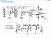
I lifted this from the oscillator schematic. It is a simple inverting op-amp amplifier. Gain is calculated by R-feedback divided by R-input.
R-input is R2, R-feedback is R3 + (R4 paralleled by the LDR). If no light is falling on the LDR it will have maximum resistance, possibly in megohms, which makes it have little effect on gain. The circuit gain then is effectively 35.2k/10k = 3.52. If the maximum light falls on the LDR its resistance drops, possibly to 10s of ohms.
upload_2020-10-23_17-50-17.gif

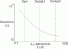
If the LDR resistance drops to 50Ω it swamps R4, so R-feedback effectively becomes 33.049kΩ and gain drops to 33.049k/10k = 3.3049. Apparently this is enough that the resistance curve controls the gain so the oscillator does not clip.
You can build your own optocoupler, from this link to another of ESP projects: https://sound-au.com/project200.htm if you cannot find one.

That is a quite ambitious project to build that oscillator, but it will be very useful if you do.
 
Last edited:
Well......This is why I was questioning how the photo resistor is powered. The project I was referring to had the photoresistor separate from the LED path.

I’ll delete the BOM above and rebuild one based on project 174
 
Now I understand where your confusion came from. Their schematics are separate and their description assumes you will know the optocoupler is a single component. I have looked at redcircuits.com projects before and not been motivated to build. Rod Elliot's documentation is usually excellent. If you buy one of his PCBs he provides 'final build instructions' with its documentation (no affiliation) according to info on his site..
 
Back
Top Bottom