• The move to the new server is done. There are some software and database maintenance updates in process. This has us passing the hat around to help out. We appreciate any donations. Seriously, even a dollar helps. The payment page may be found here - https://www.audiokarma.org/support.html

SX-1080 High End Muffled / Protection Circuit Comes On at High Volume

Are you using these as heat sinks or for handling/keeping things together while moving boards around?

Thanks!

I've used them as heatsinks to help keep the heat off the wire wrapping around the pins.

They probably help keep the wires from moving too much too when you are working around the boards.

After having two wires break in my SX-1050, I knew I had to come up with something, so I thought of using these metal paper clips and it worked for me. :yes:
 
Polarity for polyester caps?

Hi Mark,

I got all the caps in and I am looking at doing the flat amp board today. It has two polyester caps 598-DSF050J at C3 and C4.

Question:

Is there a polarity to these?

I can't see any markings on the cap and the leads are the same length.

Thanks!
 
Progress!

Flat amp board done!

I've learned sucking up the original solder with braid is the easiest way to de-solder the original caps. Some just drop right out of the board and I apply the braid to the hole to clean it a little more and I get nice clean holes.

Just waiting for a few more caps to arrive from backorder, then on to the tone control board.

Do you guys use a mask to not inhale the smoke from the soldering process? Is it toxic? Even with a fan going and a window open I was tasting the stuff.

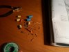
Mark, I have a noob question. See the four yellow ones in the desk shot? They are C13, C14, C15 and C16 and per the list we exchanged have been replaced by:

GWG-112 C13 100 10 CEANL 100 35 647-UKL1V101KPDANA
GWG-112 C14 100 10 CEANL 100 35 647-UKL1V101KPDANA
GWG-112 C15 100 10 CEANL 100 35 647-UKL1V101KPDANA
GWG-112 C16 100 10 CEANL 100 35 647-UKL1V101KPDANA

The two big blue ones on the desk were C17, C18 and were replaced by:

GWG-112 C17 100 25 CEA 100 35 647-UPW1V101MPD1TD
GWG-112 C18 100 25 CEA 100 35 647-UPW1V101MPD1TD

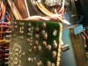
You can see the newly installed caps in the picture below.

My question: The physical size seems to have switched: the smaller yellow ones were replaced by larger ones and the big blue ones were replaced by smaller ones ( physically ). I double and triple checked all values. Is this a "newer technology" thing?
 

Attachments

  • IMG00430-20101017-2118.jpg
    IMG00430-20101017-2118.jpg
    36.8 KB · Views: 146
  • IMG00431-20101017-2118.jpg
    IMG00431-20101017-2118.jpg
    110.9 KB · Views: 148
Last edited:
Flat amp board done!

I've learned sucking up the original solder with braid is the easiest way to de-solder the original caps. Some just drop right out of the board and I apply the braid to the hole to clean it a little more and I get nice clean holes.

Congratulations! :thmbsp:

I can't seem to figure out how to use desolder braid, always can't seem to get it to work for me. :sigh:

Keep up the good work!
 
Hi Hoodcom,

braid-working problems occur when soldering iron is wether not temperature-controlled (fast enough) and/or has too low watts output. I had the same problem once and stopped using braid - what leads to other problems... until I bought appropriate working gear (Weller WTCP50 in my case). Since then - no more problems :D!

The braid sucks up a lot additional heat to that what the soldering point itself consumes, so the tip must quickly start to put in much more power to keep temperature high.
But as I read some elsewhere you're about to increase your soldering gear watt output :thmbsp: anyway! (Hope its not to much OT...)

By
 
Last edited:
What I'm doing is highlighting the solder for each component that is coming out using an orange highlighter.

I put fresh braid up against the little blob of solder and press the tip of the soldering iron on the braid and kind of jam it against the lead sticking up. When it gets heated to the right temp you see the smoke come up and the solder getting sucked into the braid. It's like a little hoover.

Key I think is getting the finer smaller braid. When I was in the electronics store they had thicker, bigger braid and it would be too bulky for this type of electronics and would take too much to heat it up.

But then I'm just a noob so take what I say and verify with others ... :)
 
<snip>

Mark, I have a noob question. See the four yellow ones in the desk shot? They are C13, C14, C15 and C16 and per the list we exchanged have been replaced by:

GWG-112 C13 100 10 CEANL 100 35 647-UKL1V101KPDANA
GWG-112 C14 100 10 CEANL 100 35 647-UKL1V101KPDANA
GWG-112 C15 100 10 CEANL 100 35 647-UKL1V101KPDANA
GWG-112 C16 100 10 CEANL 100 35 647-UKL1V101KPDANA

The two big blue ones on the desk were C17, C18 and were replaced by:

GWG-112 C17 100 25 CEA 100 35 647-UPW1V101MPD1TD
GWG-112 C18 100 25 CEA 100 35 647-UPW1V101MPD1TD

You can see the newly installed caps in the picture below.

My question: The physical size seems to have switched: the smaller yellow ones were replaced by larger ones and the big blue ones were replaced by smaller ones ( physically ). I double and triple checked all values. Is this a "newer technology" thing?

Sorry this got by me so long, it was masked by the other posts following it. Took a long search of things I posted recently to avoid things falling through the cracks. I thought the thread had turned to braid without any questions for me...


The smaller to larger substitution was the 100/10 ceanl to 100/35 UKL.

The jump in voltage made it bigger, and had more to do with what was in stock at Mouser at that time than anything else. There are a few lower in voltage showing up now, but maybe not then... I haven't looked at at the circuit to see if raising the voltage was advisable from a technical standpoint.

bigger to smaller is the general rule of thumb with 30 year old caps.
 
Got another question for you Mark

I was working on the Protection Assembly board tonight, AWM-120.

I was trying to figure out why I had an extra 47 uf 16v cap and then I noticed one of the two shown on the schematic ( C5 ) was never installed at the factory. Their soldering robots did their thing as you can see but there are empty holes on the component side.

Have a look at the pics attached - I circled the foil side and top side.

My question: should I install this cap considering they never did at the factory?
 

Attachments

  • IMG00441-20101022-2045.jpg
    IMG00441-20101022-2045.jpg
    111 KB · Views: 134
  • IMG00444-20101022-2046.jpg
    IMG00444-20101022-2046.jpg
    90.4 KB · Views: 111
After looking at the schematic C4 and C5 are connected in parallel so the
total capacitance is 94 uf.

So my question to you is what is the value of C4 on the board.
If it is 100uf it means they used one cap instead of 2

If it is 47uf then I would replace it with a 47uf and not install the other cap.

From the manual
Muting Operation When Power Supply Is turned
Off and On (Fig 8-1)

When the power supply is firt turned on, the
voltages on pins 1, 7, and 6 of PA3004 will exceed
a prescribed level. If there is no input (DC) on pin
no. 4, S2 will be off, and a charging current will
commence to flow to the timing capacitor (Ct) NOTE this is C4 and C5 on the schematic
connected to pin no. 8. Once Ct has been charged
up to a level where the voltage on pin no. 8 exceeds
a prescribed level S1 will turn on, thereby applying
a bias current from pin no. 3 to the relay driving
transistor (Qr). Consequently Qr will turn on, and
current will flow through the relay coil to activate
the relay and close the connection in the output
circuit. The time required for this connection to
close after the power supply is first turned on is
several seconds. During this period, any unwanted
transient noises will be therefore muted.

When the power supply is turned off, the input
(AC) applied to pin no. 7 ceases immediately,
resulting in S2 turning on, Ct discharging rapidly,
and S1 and Qr both turning off. The relay is thus
opened, disconnecting the output circuit.

So there ya go

 
Hi Goat

I just checked and yes it was definitely a 47uf 16v I pulled from C4 and I replaced it with the same value.

C5 was empty from the factory.
 
Thanks guys for the guidance. Four boards done now.

I'm wondering if I should touch that tuner board. seems some of the posts on here show it might be best to have that done by a pro?

Let me know,
 
Hey Folks,

Another noob question: The original ACH-085 filter caps don't show any polarity markings that I can see.

The new ones I got do show the positive post at the base by the screw terminal.

See the attached pic.

Am I correct in assuming the orange and red wires go to positive and that bridge is connecting the negative posts?

Thanks!
 

Attachments

  • IMG00451-20101023-2219.jpg
    IMG00451-20101023-2219.jpg
    87.4 KB · Views: 128
No, you are not correct. Red to positive, orange to negative. The 'common' jumper between the caps joins the negative on one cap to the positive of the other, unless you have discovered a way to get electrons from the positive terminal or holes from the negative one.

The stock caps are marked. Trust me on this.
 
Looks like on the left cap, orange is on negative, and positive is on the bridge...

I cannot tell about the other cap on the picture...

But if those caps are like the others I've seen, the black part by the screw mount indicated negative.

Someone may come in and confirm this too.

*edit*

EchoWars beat me to it.
 
Better Pic

Thanks Guys,

After your posts I shifted that bridge up and you can see the black dot was covered in the original picture.

I am trying to find markings on the base of the ACH-085 but no joy other than these black dots. Do they represent negative then?

Maybe when I pull them out it'll be on the case.

I want to replace one at a time and get the correct polarity.

See better pic below. Sorry for the finger! :D
 

Attachments

  • IMG00452-20101023-2245.jpg
    IMG00452-20101023-2245.jpg
    112.8 KB · Views: 133
Whoops

I think Echowars answered this for me.

Any further comments appreciated.

I finished recapping all my front panel boards tonight. Tomorrow is the power supply, then onward to trying to figure out how to get at the AWH-071 power amp boards.

My only setback so far has been tonight. I clipped off about a half inch piece of excess lead and it fell somewhere on top of the tuner board on the foil side and rolled somewhere. I can't find it. Nothing like trying to shake a 50 lb receiver around to try to get it to fall out. I'm a bit nervous.

The other thing is all these wires have been sitting in one position for 30 + years and don't seem to like to be moved. I'm concerned about somewhere jostling one loose from a terminal. I guess I'll know if I broke a solder joint, rattled lose a wire wrap or broke a wire when I power this thing on. I'm being very careful and checking everything 3x. Am I worried too much? Are these wires pretty durable?

On another note, once I have all these caps put in is it OK to power it up or should I get the center voltage adjustment and idle current checked? Or do that first? I don't have a multimeter but there is a tech down the road.
 
I clearly see the black, negative indicators on BOTH caps in THAT picture -

The orange wire came off the terminal held on with one black and one neutral/natural rivet, and the red wire came off the other caps' terminal that have BOTH neutral/natural colored rivets.

The central bridge connects to the black side terminals of the red wire capacitor and the non-black terminal of the orange wire cap.

edit- find the wire

and

WE ALL check every connection before powering on, looking for damage. It is a price we ALL pay...
 
Last edited:
Back
Top Bottom