• The move to the new server is done. There are some software and database maintenance updates in process. This has us passing the hat around to help out. We appreciate any donations. Seriously, even a dollar helps. The payment page may be found here - https://www.audiokarma.org/support.html

SX-1080 High End Muffled / Protection Circuit Comes On at High Volume

When you put new tires on your car, do you not get them balanced? Or get it aligned? Same principle. You put new tires on and balance and align. It'll run without rattling your teeth and leaving parts all over the road....

BRILLIANT picture, Larry.
When you work'd at your car recently, you didn't accidentally change tires :D?

Honestly, I really like these catchy clarifications. Having a 1080 dying slowly because of slacking off would be a shame (addressing myself now ... :stupid:)
 
Had a setback

Hi Mark,

I had a setback tonight.

I bought a DMM and everything was going well. My first measurements were:

Left Channel Center Voltage - .01
Right Channel Center Voltage - .03

Left Channel Idle Current - .35
Right Channel Idle Current - .34

I managed to get the left channel center voltage to 0.00 and the idle current to 30mV.

I noticed those VR's are very sensitive, only tiny movements got them to spec.

Then I worked on the right side.

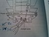
I had the idle current at 30mV but the center voltage kept showing 0.02. I tried swinging the VR2 either way to the stops and could not get it to go to 0.00. So the service manual said to snip the jumper at VR2 if I could not get 0. I did that, and afterwards disaster struck.

I don't know if I touched something - I think I might have bumped the leg or legs of transistor Q2 ( Part No. 2SC1775-E ) with my screwdriver blade but all of a sudden resistor R22 started to glow red hot and smoke. The protection circuit kicked in. I switched power off. Then I just wanted to be sure and switched it back on, and then resistor R7 started to smoke. It is wrapped in one of those white woven liner things. So I switched everything off and unplugged.

Looking at it now, resistor R22 is scorched and R7 must be but it is hidden in that white woven glove thing but there is a brown spot where the heat was.

R22 is listed as Part No. RD1/4PS 161J - Carbon Film - 160
R7 is listed as Part No. RD1/2PS 272J Carbon Film - 2.7K

R8 is identical to R7 and right next to it but I didn't see anything happen to it.

I'm assuming I need to replace these resistors. Can I ask for your help in ordering the right ones?

Should I have snipped that jumper wire?

Also, is 0.02 OK for that center voltage? Close enough?

Should I replace or check anything else?
 
Last edited:
blooie........... :yikes:

the 2sa979 dual transistor is probably at least half toast. that's the harder one to find. all that's left is new old stock - ain't makin any more new ones..
but a pair of ksa992's probably will sub in, at a small cost in performance that a new Q2 (ksc1845) may compensate for.

basically you will end up replacing almost all of the transistors on the board, as well as the damaged resistors.... not expensive but a bit of work, and HOPE that the output transistors weren't hurt - otherwise you have even more work fitting in differently shaped transistors....

this just turned into a PROJECT...
 
Ok

Where do I go for these transistors? I'm at a loss ...

Do you have any comment on my other questions?

Cheers!
 
Hi Guys,

I'm checking the service manual for model numbers of the transistors on the AWH-071 Power Amplifier Assembly board.

They are:

Q1 - 2SA979-F
Q2 - 2SC1775-E
Q3 - 2SC1885-Q or R
Q4 - 2SC1885-Q or R
Q5 - 2SA912-Q or R
Q6 - 2SD381A-M or L
Q7 - 2SB536A-M or L
Q8 - 2SC869-D or C

I tried posting these model numbers in the Mouser and I don't get a cross reference.

Anyone else bought all new transistors for these boards? Any suggestions what vendor to go to and model numbers?

Also, I have to replace a couple resistors and I'm seeing a couple dozen variations for R22 -Pioneer Part No. RD1/4PS 161J.

Could I get some advice as to which values to watch for?

Thanks!
 
Last edited:
will you kindly WAIT for me to catch up???????? and get time to DO THE REPLACEMENT LIST????

There are only so many hours in the day and my bench work time is suffering badly.

it's not even 24 hours since you posted about having a setback and finding out you blew it up.

you won't get a good cross to these old transistors, some engineering checking of the conditions in the amplifier have to be calculated to find the appropriate replacement parts numbers from mouser.com

plus you need resistors - spend the time lifting one leg or EACH of the resistors on the card looking for values more than 10 percent out of spec. and burned up looking ones that are still in spec but have been severely stressed.

Then I will have to look up THOSE too for the order.
 
Last edited:
Thanks Mark

Sorry to be so eager. I blew up my baby just minutes after I showed my wife the values on the left channel on the DMM and she figured I was pretty dang smart. When she left the room ... * poof * - she came back in to see smoke, and me with a dumbass look on my mug. Now I look like a big doofus.

Would it be prudent for me to just send you the receiver?

It would give me a chance to pay you for your work. I know you are busy and I may be waiting a while. I'm good with that. Your excellent advice and that cap list you did for me helped me immensely and worked out beautifully. I trust you and I admire your knowledge and I believe quality work is worth the wait.

Here's an update on the receiver's status:

Work Performed:

I recapped all the boards in the receiver except the tuner board, and cleaned all switches, buttons, levers, pots with Deoxit and Faderlube. I listened to it for a few nights and all functions were working beautifully until I went ahead and tried to set the center voltage and idle current and I had that accident. I dialled in the left channel power amp board to spec before I screwed up the right side.

Work Required:

1) Repair the damage I did to the right channel power amp board. ( Would that mean you'd need to RE & RE the left one to match? )
2) Check and set the center voltage and idle current
3) Recap the tuner board and check the tuner is working to spec. ( I didn't do the tuner board - I read a lot of posts about how messing with it could screw things up ). I have 98% of the caps for that board. Waiting for two backordered ones coming from Mouser.

Are you able to give me a rough cost estimate on that or would that be premature until you get a good look inside it?

Recapping and cleaning was one thing, but I think I am way over my head with the repair of the power amp board now.

Let me know if you're willing to accept it into your backlog. I don't care about the cost of freighting it down to you. I will be happy to pay it, and the return freight of course. UPS is usually pretty good for stuff like this.

Cheers!!
 
Last edited:
it's not that bad, a slow methodical attack to find the zorched resistors is all we need right now, that means taking out the transistors (testing them if possible, but cheap insurance is just putting all new in) and lifting a leg of each resistor to test, then putting it back if ok.

after we know which resistors to get, we get all the parts. I'll handle the parts numbers/where etc.... you just order and pay for them.

then under my direction, install them.

a journey is many steps, done one at a time.... I'm the map, I'm with you every step of the way and you won't get lost. You will be my hands and eyes.

it WILL get done sooner than I can get it done slipping (HAH) it into the stream here, and the $$ sting will be almost insignificant, compared to the costs (and risks) of shipping that beast hither and yon... no less crossing the border and visiting those *ahem* customs agents....


how's THAT hit ya? a "businessman" that discourages business????
I got too much work piled up already in that list to let something so small get mired in the list.

 
Last edited:
OK - I'm game.

I guess the best thing is to tear it down again? The only way to get at that board is to take out the big heat sink.

I'll check all the resistors and post back. I'm 500 miles away from home right now, it'll have to wait until next week.

You sure you don't want to do it? I am seriously apprehensive about my skill set here. I screwed up one thing, don't want to mess up anything else.

The cost of the freight and time to do it are non -issues. If I have to wait 3 months I'm fine.
 
You've got the hard part covered, you have a979's on the way in.

Now just spotting the damaged resistors to finish off the preliminaries.

The work you will be doing is with power off, and will be checked before power on.

It will be faster, my waiting list is probably over a year long... and crossing customs worries me.
 
Got the Damaged Power Amp Board Out Today

Hi Mark,

Got home last night. I've removed the damaged board.

Visual damage:

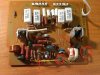
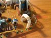
1) R7 - Service Manual Value -2.7K - p/n RD1/4PS 272J Carbon Film Resistor - Appears to be scorched -See Pic 1234
2) R8 - Service Manual Value - 2.7K - p/n RD1/4PS 272J Carbon Film Resistor - Appears to be scorched - See Pic 1236
3) R11 - Service Manual Value - 100 - p/n RD1/4PSF 101J Carbon Film Resistor - Definitely scorched. - See Pic 1233
4) R22 - Service Manual Value - 160 - p/n RD1/4PS 161J Carbon Film Resistor- Definitely scorched. See Pic 1232 ( arrow )
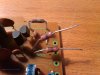
5) Loop Wire that I clipped per procedure shown in service manual ( see pics 1237,1238 ). I re-soldered it back together. It's not pretty.

See pics below of the board. On 1232 I circled or arrowed the damaged components.

I've also taken closeups of the two big transistors that have the heat sinks.

My next step is lifting the legs of all the resistors and measuring them per your previous posts.

Do I need to do that with those big white rectangular ones?
 

Attachments

  • 1232.jpg
    1232.jpg
    118.5 KB · Views: 151
  • 1233.jpg
    1233.jpg
    116 KB · Views: 123
  • 1234.jpg
    1234.jpg
    105.6 KB · Views: 114
  • 1236.jpg
    1236.jpg
    97.4 KB · Views: 118
  • 1237.jpg
    1237.jpg
    84.6 KB · Views: 109
  • 1238.jpg
    1238.jpg
    114 KB · Views: 94
Pics of Transistors

Per previous post due to limite on number of pics per post.
 

Attachments

  • IMG00485-20101106-1258.jpg
    IMG00485-20101106-1258.jpg
    103.6 KB · Views: 99
  • IMG00487-20101106-1259.jpg
    IMG00487-20101106-1259.jpg
    82.4 KB · Views: 93
Measured Resistor Values

Hi Mark,

Per your instructions, I de-soldered and lifted one leg of all resistors of all types on the board and measured them. Here are my results. I hope the format works for you. I have a "thumbs down" emoticon beside the obvious failures, but you might want to scan the rest of the results?

R1 - RD1/4PS 564J Carbon Film - SM Value 560k - Measured Value - .561 w/ DMM set at 2M
R2 - RD1/4PS 102J Carbon Film - SM Value 1k - Measured Value - 1.00 w/DMM set at 20k
R3 - RD1/4PS 102J Carbon Film - SM Value 1k - Measured Value - 1.00 w/ DMM set at 20k
R4 - RD1/4PS 243J Carbon Film - SM Value 24k - Measured Value - 12.1 w/ DMM set at 200k :thumbsdn:
R5 - RD1/4PS 124J Carbon Film - SM Value 120k - Measured Value - 47.5 w/DMM set at 200k :thumbsdn:
R6 - RD1/4PS 243J Carbon Film - SM Value 24k - Measured value - 24 w/ DMM set at 200k
R7 - RD1/4PS 272J Carbon Film - SM Value 2.7k - Measured value - 2.71 w/ DMM set at 20k - this one got hot in the accident but doesn't seem to have suffered?
R8 - RD1/4PS 272J Carbon Film - SM Value 2.7k - Measured value - 2.68 w/ DMM set at 20k
R9 - RD1/4PSF 151J Carbon Film - SM Value 150 - Measured value - 149.9 w/ DMM set at 200k
R10 - RS1P 103J - Metal Oxide - SM Value 10k - Measured value - 9.95 w/ DMM set at 2ok
R11 - RD1/4PSF 101J Carbon Film - SM Value 100 - Measured Value - N/A - No reading - Scorched :thumbsdn:
R12 - RD1/4PSF 151J Carbon Film - SM Value 150 - Measured value - 150 w/ DMM set at 200k
R13 - RD1/4PS 562J Carbon Film - SM Value 5.6k - Measured Value - 5.68 w/ DMM set at 20k
R14 - RD1/2PSF 151J Carbon Film - SM Value 150 - Measured Value - 148.6 w/DMM set at 200
R15 - RD1/2PSF 151J Carbon Film - SM Value 150 - Measured Value - 148.4 w/DMM set at 200k
R16 - RT5B 0R5K Wier Wound - SM Value 0.5 - Measured Value - 00.5 w/DMM set at 200k
R17 - RT5B 0R5K Wier Wound - SM Value 0.5 - Measured Value - 00.5 w/DMM set at 200k
R18 - RT5B 0R5K Wier Wound - SM Value 0.5 - Measured Value - 00.5 w/DMM set at 200k
R19 - RT5B 0R5K Wier Wound - SM Value 0.5 - Measured Value - 00.5 w/DMM set at 200k
R20 - RS2P 100J - Metal Oxide - SM Value 10 - Measured Value - 10 w/DMM set at 200k
R21 - RS1P 562J - Metal Oxide - SM Value 5.6k - Measured Value - 5.68 w/DMM set at 20k
R22 - RD1/4PS 161J Carbon Film - SM Value 160 - Measured Value - N/A - No reading - Scorched :thumbsdn:
R23 - RD1/4PS 220J - Carbon Film - SM Value 22 - Measured Value - 22 - w/DMM set at 200k
R24 - RD1/4PS 220J - Carbon Film - SM Value 22 - Measured Value - 22 - w/DMM set at 200k
R25 - RD1/4PS 220J - Carbon Film - SM Value 22 - Measured Value - 22.2 - w/DMM set at 200k
R26 - RD1/4PS 220J - Carbon Film - SM Value 22 - Measured Value - 22 - w/DMM set at 200k
R27 - RS2P 100J - Metal Oxide - SM Value 10 - Measured Value - 9.6 - w/DMM set at 200k
R28 - RD1/4PSF 132J Carbon Film - SM Value 1.3k - Measured value - 1.3 w/ DMM set at 20k
R29 - RD1/4PSF 132J Carbon Film - SM Value 1.3k - Measured value - 1.29 w/ DMM set at 20k
R30 - RD 1/4PS 153J Carbon Film - SM Value 15k - Measured Value - 15.0 w/DMM set at 200k
R31 - RD 1/4PS 153J Carbon Film - SM Value 15k - Measured Value - 14.9 w/DMM set at 200k
R32 - RD1/4PS 272J Carbon Film - SM Value 2.7k - Measured value - 2.7 w/ DMM set at 20k
R33 - RD1/4PS 563J Carbon Film - SM Value 56k - Measured Value - 56.3w/ DMM set at 200k

Cheers!
 
Last edited:
I can't see any colors on R11 or R22 - they are scorched.

But - according to Dannyg's site:

R4 is actually a 12 kohm +/- 5% ( not the 24k the manual shows )
R5 is actually a 47 kohms +/- 5% ( not the 120k the manual shows )

Holy smokes. That's dead on to what I measured!! :banana:

So the manual is wrong!

So cool! I just learned something tonight!

So what shall we do about R7 and R8 which got heated but don't seem to be affected? They are big honkers compared to the other carbon resistors.
 
One more detail I thought you might want to know, I realize it is Q2 the 2SC1775A that I bumped into that sparked and caused the meltdown, the two legs closest the variable resistor I was trying to adjust.

FYI for troubleshooting purposes.

Cheers!
 
What do you mean R7 & R8 are larger?

R7 - RD1/4PS 272J Carbon Film - SM Value 2.7k - Measured value - 2.71 w/ DMM set at 20k - this one got hot in the accident but doesn't seem to have suffered?
R8 - RD1/4PS 272J Carbon Film - SM Value 2.7k - Measured value - 2.68 w/ DMM set at 20k


Both are supposed to be 1/4 watt:
71-CCF07-J-2.7K

you can get them too...
 
You can see the two of them in Pic 1236. Big thick leads. Bigger girth than all the other carbon resistors. Compare to the slender zorched one in that pic.
 
I see you've posted the replacement numbers for the resistors. Should I wait until you provide the transistor list before I order?
 
Back
Top Bottom