

You are using an out of date browser. It may not display this or other websites correctly.
You should upgrade or use an alternative browser.
You should upgrade or use an alternative browser.
sx-1250 power amp SMOKED help
- Thread starter arranb
- Start date

I'm sorry if I'm being impatient and rushing but, Me and my wife have a baby due on December 21st and it's gonna be a while before I can get back to this. I really wanna get it up and running before the baby. Then do a complete restore. I am trying to figure out the meat and potatoes before cleaning it top to bottom. I'm thinking something is wrong with my one awh-048. I am going to compare readings out of the receiver side by side with the one I could adjust properly and hopefully find something bad. Once again I know you all have lives to and I greatly appreciate the help I've received so far. I'm not ungrateful in any way and if there is something I can do for you please ask.
Thanks again.
Thanks again.

ok, look for 0.6v between each transistor's emitter (black dmm lead) and base (red dmm lead). plus or minus polarity depending upon npn or pnp...
Then post both sets of voltages. remember the errors cascade AND the entire amp is balanced around the feedback system.
INSULATE all but the TIPS of your probes.
Then post both sets of voltages. remember the errors cascade AND the entire amp is balanced around the feedback system.
INSULATE all but the TIPS of your probes.
Ok, that's tin 63, lead 37 solder, it's fine... temperature 180 degrees C but set the iron for 195 C to handle the older possible 60/40 solder, and the mixing of the two with possible untoward effects.
Last edited:
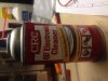
my soldering Iron only goes down to 200c. I'm trying to take a good pic to let you see what happened to one of the boards either when it overheated and SMOKED or when I used this stuff to try and clean it. I'm sure you can see how it looks like some real bad sunburn peeling and the other looks like smooth skin! I've gone over both boards with my DMM checking resistance knowing that I can adjust one to the specs and the other I could not. I found differences but nothing that seems major, But I am new at this so what I'd like to do is clean this ugly board up and work with something I visually see there isn't anything grounding out on each other. I fly rc planes and everything has to be perfect or else.....Actually you have more room for error doing that than this! IMO
I'm starting to feel bad for my poor sx-1250 that this is the amp I am learning on. ity: should I put her away and practice on something less valuable?
I'm starting to feel bad for my poor sx-1250 that this is the amp I am learning on.
ity: should I put her away and practice on something less valuable?Attachments

ok, look for 0.6v between each transistor's emitter (black dmm lead) and base (red dmm lead). plus or minus polarity depending upon npn or pnp...
Then post both sets of voltages. remember the errors cascade AND the entire amp is balanced around the feedback system.
INSULATE all but the TIPS of your probes.
So do I check this with the amp powered up on house power and the board kinda hanging out? I hope that wasn't a dumb question.
my soldering Iron only goes down to 200c. I'm trying to take a good pic to let you see what happened to one of the boards either when it overheated and SMOKED or when I used this stuff to try and clean it. I'm sure you can see how it looks like some real bad sunburn peeling and the other looks like smooth skin! I've gone over both boards with my DMM checking resistance knowing that I can adjust one to the specs and the other I could not. I found differences but nothing that seems major, But I am new at this so what I'd like to do is clean this ugly board up and work with something I visually see there isn't anything grounding out on each other. I fly rc planes and everything has to be perfect or else.....Actually you have more room for error doing that than this! IMO
I'm starting to feel bad for my poor sx-1250 that this is the amp I am learning on.
Is that a hot air station you are using for your soldering? You have a few damaged pads on that board if you are using that hot air station.
It's a yihua 853d I bought off Amazon. It has a voltage checker, a rework heater and the soldering iron. Was it a bad buy? or just the wrong tool for this kind of work? One of my customers said this would be the soldering station for whatever I needed. But honestly, I trust you guys more at this point. I'm 35 and have been soldering since I was 10 but didn't know what a solder pump was until I ventured into this little (big project). I will say I'm all in now! I love doing this stuff. Learning how things works excites me. whats your thoughts on the solder pumps? I think they are pulling the pads up!
It's a yihua 853d I bought off Amazon. It has a voltage checker, a rework heater and the soldering iron. Was it a bad buy? or just the wrong tool for this kind of work? One of my customers said this would be the soldering station for whatever I needed. But honestly, I trust you guys more at this point. I'm 35 and have been soldering since I was 10 but didn't know what a solder pump was until I ventured into this little (big project). I will say I'm all in now! I love doing this stuff. Learning how things works excites me. whats your thoughts on the solder pumps? I think they are pulling the pads up!
Just was wondering as I did not see the iron in that photo. Looks like a well equipped unit.

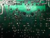
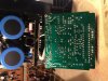
Here are a few pics from the awh-048 board thats giving me the problem. I cleaned it with alcohol this morning. I tried before but now realize you basically have to give it a bath to get it clean. Didn't submerge it but scrubbed a bit and then squirted the alcohol over it to rinse it. Wow is all I can say. Must have been a bunch of old flux on the board.
Attachments
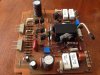

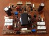
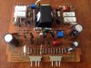
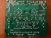
Even though the connections look bad I did check to make sure they have good continuity. MTF, do I do this with the board plugged in on house power?
"ok, look for 0.6v between each transistor's emitter (black dmm lead) and base (red dmm lead). plus or minus polarity depending upon npn or pnp...
Then post both sets of voltages. remember the errors cascade AND the entire amp is balanced around the feedback system.
INSULATE all but the TIPS of your probes."
"ok, look for 0.6v between each transistor's emitter (black dmm lead) and base (red dmm lead). plus or minus polarity depending upon npn or pnp...
Then post both sets of voltages. remember the errors cascade AND the entire amp is balanced around the feedback system.
INSULATE all but the TIPS of your probes."
I'm worried that some of those solder joints may be intermittent, it looks a lot better cleaned, but those iffy joints appearance didn't improve in that latest picture...
be VERY VERY careful about shorts. insulate all but the tiniest portion of the end of the probe tip on ANY probe that isn't clipped to ground in a wide open area.
how about a picture of the business end of your soldering iron, and the desoldering tip (if there is one). The tip needs to be as clean and bright as a new solder joint. Otherwise heat transfer will stink... and so will the joints. Soldering is a real mix of technique and equipment, but if the equipment has a problem, all the technique in the world won't set things right.
I literally keep an open container of flux that I poke the tip into when things start to slightly bog down. You should be able to get on a pad and solder it in less than 5 seconds. With a vacuum desoldering tip (foot operated) you should also be off the joint in less than the 5 seconds - usually far less.
When I set either iron on the pad, I usually have a solder wire between the tip and the pad, pulling the wire just after it melts say 1 mm, to "wet" the tip and joint together. THEN I apply the rest of the needed solder to the joint to the PAD area, not the iron, to form the pool once the pad is hot enough to melt it. Applying to the tip while the pad is too cool, just forms "cold" nuggets that sit above the pad, not flow across it.
be VERY VERY careful about shorts. insulate all but the tiniest portion of the end of the probe tip on ANY probe that isn't clipped to ground in a wide open area.
how about a picture of the business end of your soldering iron, and the desoldering tip (if there is one). The tip needs to be as clean and bright as a new solder joint. Otherwise heat transfer will stink... and so will the joints. Soldering is a real mix of technique and equipment, but if the equipment has a problem, all the technique in the world won't set things right.
I literally keep an open container of flux that I poke the tip into when things start to slightly bog down. You should be able to get on a pad and solder it in less than 5 seconds. With a vacuum desoldering tip (foot operated) you should also be off the joint in less than the 5 seconds - usually far less.
When I set either iron on the pad, I usually have a solder wire between the tip and the pad, pulling the wire just after it melts say 1 mm, to "wet" the tip and joint together. THEN I apply the rest of the needed solder to the joint to the PAD area, not the iron, to form the pool once the pad is hot enough to melt it. Applying to the tip while the pad is too cool, just forms "cold" nuggets that sit above the pad, not flow across it.
Last edited:
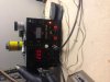
Mark I'm a bit confused on how you want me to check for 0.6v on the board awh-o48. I understand the part about black lead emitter and red lead base. Do I do this with the board kinda hanging out of the amp so I can access the transistor points? Also do I plug all 5 connectors in and are the preamp jumpers supposed to be in or out? Here Is a picture of what I was going to try but stopped before I mess something up.
And here is that pic of the business end's tip.
And here is that pic of the business end's tip.
Attachments
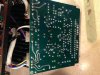
a 180 degree flip on the axis of the board edge connectors, sticking the board out through the bottom of the chassis with the unit standing on it's side, with the transistor connectors disconnected and the stv diode hanging loose.
Power on, CAREFULLY. Watch out for shorts, tape things that look iffy.
This type of amplifier will balance without the output transistors connected.
Power on, CAREFULLY. Watch out for shorts, tape things that look iffy.
This type of amplifier will balance without the output transistors connected.
Last edited:

DrumminDaddy
Hit it, Baby !!
remember the errors cascade AND the entire amp is balanced around the feedback system.
Mark, I'm another newb 'round here that's been following this thread as I've got the same receiver and I'm also interested in troubleshooting. Just a couple things if I may interject;
1) What do you mean by the term 'errors cascade'? Are you simply referring to the ranging issues of a dmm or is there something I'm missing regarding checking these components in circuit?
2) Thank you ever so much for the time you put into this forum to help folks with this stuff.
errors cascade:
garbage in, garbage out....
a small error in the front end of a feedback circuit will produce increasingly abnormal readings in GOOD circuits as it moves along the stages within the feedback system. Usually it causes the amp to "rail" which is like a teeter-totter hitting the ground on one side - it can't go any further.
The breaking point of this analogy is while the teeter-totter hits the "ground" the amp will hit the positive or negative power supply maximum - the power supply lines are sometimes called "rails".
garbage in, garbage out....
a small error in the front end of a feedback circuit will produce increasingly abnormal readings in GOOD circuits as it moves along the stages within the feedback system. Usually it causes the amp to "rail" which is like a teeter-totter hitting the ground on one side - it can't go any further.
The breaking point of this analogy is while the teeter-totter hits the "ground" the amp will hit the positive or negative power supply maximum - the power supply lines are sometimes called "rails".
DrumminDaddy
Hit it, Baby !!
errors cascade:
garbage in, garbage out.....
Understood. While still fuzzy on the details, I comprehend the principle now.
Thanks again!
a 180 degree flip on the axis of the board edge connectors, sticking the board out through the bottom of the chassis with the unit standing on it's side, with the transistor connectors disconnected and the stv diode hanging loose.
Power on, CAREFULLY. Watch out for shorts, tape things that look iffy.
This type of amplifier will balance without the output transistors connected.
So my pictures above are correct except that I have the transistors plugged in?
So my pictures above are correct except that I have the transistors plugged in?
Your picture leads me to believe that the two chassis connectors (3 pins each ) are NOT plugged in. THEY carry the regulated voltages (+65-pin 3, -65 pin 2) to RUN the board as well as several (pin 5 signal input ground REFERENCE, pin 6 regulated power supply RETURN) grounds. The pin 1 over current protect output, and the pin 4 signal input can be neglected for now.
IF you have it arranged so ALL connectors can be plugged in and take readings, there is no need to disconnect the output transistors.
You cleaned the back of the board, so there is "room" on it to mark the transistor positions in advance of probing, to easily identify the positions.
A fine sharpie works fine, then acetone can take it off later. I do it some, when troubleshooting gets involved.