You are using an out of date browser. It may not display this or other websites correctly.
You should upgrade or use an alternative browser.
You should upgrade or use an alternative browser.
sx-1250 power amp SMOKED help
- Thread starter arranb
- Start date

Tonight's fun
So here is the list of parts that arrived today. Tonight I am going to install them very carefully. A couple of the board pieces seem to be lifting from the repeat replacement of parts. What is the best way to repair them?
QUOTE=zebulon1;8289592]sx-1250,power,supply,stabilizer,ok,,,,,
sx-1250,awr-106,c1,220,80,cea,,220,100,647-UPW2A221MHD
sx-1250,awr-106,c2,220,80,cea,,220,100,647-UPW2A221MHD
sx-1250,awr-106,C5,47,35,cea,,47,35,647-UPW1V470MED
sx-1250,awr-106,C6,47,35,cea,,47,35,647-UPW1V470MED
sx-1250,awr-106,C7,22,50,cea,,22,50,647-UPW1H220MDD
sx-1250,awr-106,C8,22,50,cea,,22,50,647-UPW1H220MDD
sx-1250,awr-106,C9,100,35,cea,,100,50,647-UPW1H101MPD
sx-1250,awr-106,C10,100,35,cea,,100,50,647-UPW1H101MPD
sx-1250,awr-106,C11,47,80,cea,,47,100,647-UPW2A470MPD
sx-1250,awr-106,C12,47,80,cea,,47,100,647-UPW2A470MPD
sx-1250,awr-106,C13,1000,25,ceb,,1000,35,647-TVX1V102MCD
sx-1250,awr-106,C15,47,10,cea,,47,10,647-UPW1A470MDD6
sx-1250,awr-106,C16,22,10,cea,,22,10,647-UPW1A220MDD
sx-1250,awr-106,C17,220,16,cea,,220,25,647-UPW1E221MPD1TD
sx-1250,awr-106,C18,47,10,cea,,47,10,647-UPW1A470MDD6
sx-1250,awr-106,C19,47,10,cea,,47,10,647-UPW1A470MDD6
sx-1250,awr-106,q1,2sd313,pass +65,,,,,512-KSC2073TU
sx-1250,awr-106,q2,2sc869,darl,,,,,512-KSC2383YTA
sx-1250,awr-106,q3,2sc1318,err-amp,,,,,512-KSC1845FTA
sx-1250,awr-106,q4,2sc1384,pass +25,,,,,512-KSC2690AYS
sx-1250,awr-106,q5,2sb507,pass -65,,,,,512-KSA940TU
sx-1250,awr-106,q6,2sa628,darl,,,,,512-KSA1013YBU
sx-1250,awr-106,q7,2sa720,err-amp,,,,,512-KSA992FBU
sx-1250,awr-106,q8,2sa684,pass -25,,,,,512-KSA1220AYS
sx-1250,awr-106,q9,2sd325,pass +13,,,,,512-KSC2073TU
sx-1250,awr-106,q10,2sc945,darl,,,,,512-KSC2383YTA
sx-1250,awr-106,q11,2sc945,err-amp,,,,,512-KSC1845FTA
sx-1250,awr-106,q12,2sd325,pass +5.5 ,,,,,512-KSC2073TU
sx-1250,awr-106,q13,2sc945,darl,,,,,512-KSC2383YTA
sx-1250,awr-106,d1,wz-240,,,,,,512-1N5252B
sx-1250,awr-106,d3,wz-240,,,,,,512-1N5252B
sx-1250,awr-106,d5,wz-061,,,,,,512-1N5234B
sx-1250,awr-106,d2,1s2473,,,,,,512-1n4148
sx-1250,awr-106,d4,1s2473,,,,,,512-1n4148
sx-1250,awr-106,vr1,4.7k,1 turn,,,,,652-3386H-1-502LF
sx-1250,awr-106,vr2,4.7k,1 turn,,,,,652-3386H-1-502LF
sx-1250,awr-106,R13,680,2W mox,,,,,660-MO2C681J
sx-1250,awr-106,R14,1.5K,2W mox,,,,,660-MO2C152J
sx-1250,awr-106,R18,100,2W mox,,,,,660-MO2C101J[/QUOTE]
So here is the list of parts that arrived today. Tonight I am going to install them very carefully. A couple of the board pieces seem to be lifting from the repeat replacement of parts. What is the best way to repair them?
QUOTE=zebulon1;8289592]sx-1250,power,supply,stabilizer,ok,,,,,
sx-1250,awr-106,c1,220,80,cea,,220,100,647-UPW2A221MHD
sx-1250,awr-106,c2,220,80,cea,,220,100,647-UPW2A221MHD
sx-1250,awr-106,C5,47,35,cea,,47,35,647-UPW1V470MED
sx-1250,awr-106,C6,47,35,cea,,47,35,647-UPW1V470MED
sx-1250,awr-106,C7,22,50,cea,,22,50,647-UPW1H220MDD
sx-1250,awr-106,C8,22,50,cea,,22,50,647-UPW1H220MDD
sx-1250,awr-106,C9,100,35,cea,,100,50,647-UPW1H101MPD
sx-1250,awr-106,C10,100,35,cea,,100,50,647-UPW1H101MPD
sx-1250,awr-106,C11,47,80,cea,,47,100,647-UPW2A470MPD
sx-1250,awr-106,C12,47,80,cea,,47,100,647-UPW2A470MPD
sx-1250,awr-106,C13,1000,25,ceb,,1000,35,647-TVX1V102MCD
sx-1250,awr-106,C15,47,10,cea,,47,10,647-UPW1A470MDD6
sx-1250,awr-106,C16,22,10,cea,,22,10,647-UPW1A220MDD
sx-1250,awr-106,C17,220,16,cea,,220,25,647-UPW1E221MPD1TD
sx-1250,awr-106,C18,47,10,cea,,47,10,647-UPW1A470MDD6
sx-1250,awr-106,C19,47,10,cea,,47,10,647-UPW1A470MDD6
sx-1250,awr-106,q1,2sd313,pass +65,,,,,512-KSC2073TU
sx-1250,awr-106,q2,2sc869,darl,,,,,512-KSC2383YTA
sx-1250,awr-106,q3,2sc1318,err-amp,,,,,512-KSC1845FTA
sx-1250,awr-106,q4,2sc1384,pass +25,,,,,512-KSC2690AYS
sx-1250,awr-106,q5,2sb507,pass -65,,,,,512-KSA940TU
sx-1250,awr-106,q6,2sa628,darl,,,,,512-KSA1013YBU
sx-1250,awr-106,q7,2sa720,err-amp,,,,,512-KSA992FBU
sx-1250,awr-106,q8,2sa684,pass -25,,,,,512-KSA1220AYS
sx-1250,awr-106,q9,2sd325,pass +13,,,,,512-KSC2073TU
sx-1250,awr-106,q10,2sc945,darl,,,,,512-KSC2383YTA
sx-1250,awr-106,q11,2sc945,err-amp,,,,,512-KSC1845FTA
sx-1250,awr-106,q12,2sd325,pass +5.5 ,,,,,512-KSC2073TU
sx-1250,awr-106,q13,2sc945,darl,,,,,512-KSC2383YTA
sx-1250,awr-106,d1,wz-240,,,,,,512-1N5252B
sx-1250,awr-106,d3,wz-240,,,,,,512-1N5252B
sx-1250,awr-106,d5,wz-061,,,,,,512-1N5234B
sx-1250,awr-106,d2,1s2473,,,,,,512-1n4148
sx-1250,awr-106,d4,1s2473,,,,,,512-1n4148
sx-1250,awr-106,vr1,4.7k,1 turn,,,,,652-3386H-1-502LF
sx-1250,awr-106,vr2,4.7k,1 turn,,,,,652-3386H-1-502LF
sx-1250,awr-106,R13,680,2W mox,,,,,660-MO2C681J
sx-1250,awr-106,R14,1.5K,2W mox,,,,,660-MO2C152J
sx-1250,awr-106,R18,100,2W mox,,,,,660-MO2C101J[/QUOTE]
I replaced all the parts listed above last night and here are my new readings with only the awr-106a plugged in on a 100w DBT.
awr.106 pin 1 -70.4v -62v raw dc speaker power out
awr.106 pin 2 +70.5v +62v raw dc speaker power out
awr.106 pin 3 0mv 0v ground
awr.106 pin 4 +1mv should be no reading AC power input
awr.106 pin 5 -1.0mv should be no reading AC power input
awr.106 pin 6 +86.8v +85v raw dc in
awr.106 pin 7 +23.83v +23v raw dc in
awr.106 pin 8 +5.58v +5.4v regulated dc out
awr.106 pin 9 +13.57v+13.5v regulated dc out
awr.106 pin 10 +23.97v +25v regulated dc out
awr.106 pin 11 +62.0v +65v regulated dc out
awr.106 pin 12 +0.2mv -75v ground IS THIS CORRECT?
awr.106 pin 13 -60.2v -65v regulated dc out
awr.106 pin 14 -23.70-25v regulated dc out
awr.106 pin 15 -87.4v -87.5v raw dc in
awr.106 pin 16 -60.3v -65v regulated dc out test pin
awr.106 pin 17 +62.5v +65v regulated dc out
I see a lot of numbers much closer to where they are supposed, Am I on the right track?
awr.106 pin 1 -70.4v -62v raw dc speaker power out
awr.106 pin 2 +70.5v +62v raw dc speaker power out
awr.106 pin 3 0mv 0v ground
awr.106 pin 4 +1mv should be no reading AC power input
awr.106 pin 5 -1.0mv should be no reading AC power input
awr.106 pin 6 +86.8v +85v raw dc in
awr.106 pin 7 +23.83v +23v raw dc in
awr.106 pin 8 +5.58v +5.4v regulated dc out
awr.106 pin 9 +13.57v+13.5v regulated dc out
awr.106 pin 10 +23.97v +25v regulated dc out
awr.106 pin 11 +62.0v +65v regulated dc out
awr.106 pin 12 +0.2mv -75v ground IS THIS CORRECT?
awr.106 pin 13 -60.2v -65v regulated dc out
awr.106 pin 14 -23.70-25v regulated dc out
awr.106 pin 15 -87.4v -87.5v raw dc in
awr.106 pin 16 -60.3v -65v regulated dc out test pin
awr.106 pin 17 +62.5v +65v regulated dc out
I see a lot of numbers much closer to where they are supposed, Am I on the right track?
Last edited:

Recheck pin 14. I think you probably meant (-) on your reading.
Pin 12 is the regulated ground. Your readings are correct.
Looks good!
Amp boards unpluged, top and bottom. Full house current.
Set the regulated voltages to +-65v.
Recheck all the voltages one more time.
Check the set's functions; lights, tuner for signal, stereo light.
Where are you on the amp boards?
Pin 12 is the regulated ground. Your readings are correct.
Looks good!
Amp boards unpluged, top and bottom. Full house current.
Set the regulated voltages to +-65v.
Recheck all the voltages one more time.
Check the set's functions; lights, tuner for signal, stereo light.
Where are you on the amp boards?
Back on DBT!
One Amp board at a time.
Check the settings before moving to the other one. If idle was set before it will be showing a lower setting, just leave it.
The protection will be acting weird. Ignore it for now.
Now the amp boards were rebuilt and working? Then you moved to the Stabilizer and that's when all went down hill?
One Amp board at a time.
Check the settings before moving to the other one. If idle was set before it will be showing a lower setting, just leave it.
The protection will be acting weird. Ignore it for now.
Now the amp boards were rebuilt and working? Then you moved to the Stabilizer and that's when all went down hill?
Last edited:
yes the amp boards were working and then i goofed and installed the wrong transistor on q5 of the stabilizer board. I installed a 863-mje15032g instead of a 863-mje15033g. I have the voltages set to 65- and 65+ and the right amp board set properly as of a minute ago. the vr2 on the left amp board will only adjust from 75.9 - 77.0 mv. Any thought of what could be wrong here? Should I install the old vr2 and give it a try or is it possible a resistor may be bad?
 o.k. new dilemma here. I have been running into this on several of my solder connections. I think this is why the vr2 may not have been adjusting. I am using a temperature controlled soldering station. I have it set to 250c I'm also using a solder pump to remove the old solder. How do I fix this BIG issue I have?
When on the DBT your voltages are reduced. You just needed to check the amp settings.
They were probably OK.
The Idle is set only after going on house power.
Set the station to 185c.
Is that a picture of the trimmer trace?
They were probably OK.
The Idle is set only after going on house power.
Set the station to 185c.
Is that a picture of the trimmer trace?
Last edited:
View attachment 558381o.k. new dilemma here. I have been running into this on several of my solder connections. I think this is why the vr2 may not have been adjusting. I am using a temperature controlled soldering station. I have it set to 250c I'm also using a solder pump to remove the old solder. How do I fix this BIG issue I have?
Looks like you more than one solder pad that left the board and some other soldering to redo. There are several cold joints that don't look good. The final solder joint should be nice and shiny not dark. Are you using the correct flux? You can also use your dmm to check for continuity between the components on the same circuit.
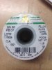
I am using FLUX GLOW CORE 2.5% I purchased it from mouser. Part number PB37 LOT#C-79028 DIA: .032" Is that ok? I agree this stuff makes a real mess but I haven't been soldering anything other that wires my entire life. I am open to any and all suggestions. I'd like everything to look nice and clean. What are cold joints? I have used my DMM to check connections also. Off the subject I am listening to the Romans on My Pilot tubes receiver and Bozak A300 speakers that I traded a drill for both! They sound amazing. I can't wait to hear this sx-1250! Obviously I'm gonna have to get some speakers that can handle more!
I am using FLUX GLOW CORE 2.5% I purchased it from mouser. Part number PB37 LOT#C-79028 DIA: .032" Is that ok? I agree this stuff makes a real mess but I haven't been soldering anything other that wires my entire life. I am open to any and all suggestions. I'd like everything to look nice and clean. What are cold joints? I have used my DMM to check connections also. Off the subject I am listening to the Romans on My Pilot tubes receiver and Bozak A300 speakers that I traded a drill for both! They sound amazing. I can't wait to hear this sx-1250! Obviously I'm gonna have to get some speakers that can handle more!
The flux is OK as long as it is for rosin core solder. You will need to wait for the experts to way in on the procedures to fix the receiver.
The flux is OK as long as it is for rosin core solder. You will need to wait for the experts to way in on the procedures to fix the receiver.
Cold solder joint.. see image and I have marked some of the solder pads that need attention with a second image. Do you know how to check for continuity between two pads on the same trace? the red line shows a trace between two pads. Set meter on ohms, red probe on one pad and the black probe on the other pad on the same foil/trace or circuit. If there is almost zero ohms then the circuit is good, if the resistance is high then there is something wrong with that circuit.
I would wait until the experts way in on fixing this one..
Attachments
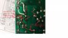
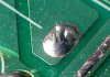

perhaps mailing the board to someone a bit more experienced is in order for some quick straightening out. Then you will SEE what good vs not good is...
That missing pad isn't the full problem, since it is the end of the VR2 idle current pot and the wiper is still connected, BUT if THAT circuit opens up, BLOOIEEEEEEE .
Your problem may be that you are mixing lead free and old lead solder at a wrong temperature on the iron. I can't tell because that isn't a mouser number. Mouser numbers are ###-## and I have tried to determine it's content from mouser for the last 5 minutes...
There are some joints in those pictures that i would give people grief over.
That missing pad isn't the full problem, since it is the end of the VR2 idle current pot and the wiper is still connected, BUT if THAT circuit opens up, BLOOIEEEEEEE .
Your problem may be that you are mixing lead free and old lead solder at a wrong temperature on the iron. I can't tell because that isn't a mouser number. Mouser numbers are ###-## and I have tried to determine it's content from mouser for the last 5 minutes...
There are some joints in those pictures that i would give people grief over.
Mark I am going to post a picture of the solder in a minute. I managed to make the connections work. I am still having a problem getting the idles to set correctly on this amp board. The vr1 won't go any lower than 48.7 mv. the other amp board went to the specified voltages. I'm not 100% sure but I think I may have some kind of ground problem, when the radio is on and playing music if I touch the far left pot right next to the power switch I get a buzzing noise through my test speakers and a little tingle like say if you were a singer in a band and got zapped by the mic.
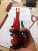
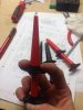
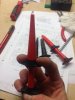
Here is a picture of my new Bozak speakers and the Pilot tubed receiver I traded for a drill (which sound amazing!) Also a picture of the solder I used and a picture of a couple cool tools I bought off the tool truck today. I like em, Makes it easier to get to pin #9 on the left board without touching things you shouldn't touch. If you guys ever need help with diagnostics on a passenger vehicle just ask me. Thanks what I do for a living... I'll gladly help if I can. I have the stv 3's ready to send to ya mark. just message me your address and I'll send em out this week.