

You are using an out of date browser. It may not display this or other websites correctly.
You should upgrade or use an alternative browser.
You should upgrade or use an alternative browser.

J A
Active Member
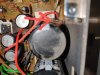
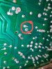
So, I'm in the process of attempting this measurement but here is a photo of that resistor. Obviously I'm not a regular electronics person but this doesn't look what I would describe as "good". That is r410 that the poorly drawn arrow is pointing to. At R410 I measured 166Ω on the last one but I took a lot of measurements and that was by far the highest. I could only get a measurement once at each polarity (example red on one side would only measure once, then switch red and black and measure again). I'm guessing that's normal? Electrons shifting from one side to the other?? idk, anyway, another note is that I've enclosed a photo of the -side of c413 solder. The reason I've added it is only because it is different than the others in that it doesn't connect with the nearby solder point like the others do. May not matter but thought it was worth mentioning. As a layman it just looks different but it may have value for you.
Attachments
Last edited:

petehall347
the brandy coffee man
r410 appears to have expired .
best also check r345 r346 both 100 ohms .
best also check r345 r346 both 100 ohms .
petehall347
the brandy coffee man
1/4w 5% unless stated otherwise .
this one looks like 1/4W
this one looks like 1/4W
petehall347
the brandy coffee man
one or both output power packs might be bad ..do they unplug or are they soldered in ?
also best check the transistors on the amp board ..something caused that resistor to burn
also best check the transistors on the amp board ..something caused that resistor to burn
petehall347
the brandy coffee man
maybe best remove them for now . you will need to add some resistors for testing purposes whilst the packs are removed .

merlynski
Curmudgeon Electronicist
The Power Pack STK is a current amplifier power output stage in one package, They are virtually impossible to test manually. Sometimes, if they are bad they can be tested with the meter to see if they are shorted internally. Since you had sound from both channels (albeit with hum) they are probably OK for now. Lets not get off track from the power supply problem.
R410 measurement look like your meter is autoranging because it cannot figure out what it should be measuring. There are multiple possibilities for a resistor reading low while in circuit, but nothing (unpowered) that can make it read high.
R410 should have a color code striping of brown black brown gold for a 100Ω 5% resistor. Unsolder and remove it. The resistor your arrow points at looks like brown black green, which would be 1MΩ.
Was this unit working and then died, or did it have the hum when you got it?
R410 measurement look like your meter is autoranging because it cannot figure out what it should be measuring. There are multiple possibilities for a resistor reading low while in circuit, but nothing (unpowered) that can make it read high.
R410 should have a color code striping of brown black brown gold for a 100Ω 5% resistor. Unsolder and remove it. The resistor your arrow points at looks like brown black green, which would be 1MΩ.
Was this unit working and then died, or did it have the hum when you got it?
petehall347
the brandy coffee man
i was thinking if the packs are out of circuit then they cant get damaged . then test the rest of the circuit and see if its safe to put the packs back in .
J A
Active Member
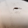
Ok, got it off the board. I believe there's some brown black and gold but it's pretty cruddy in general so tough to tell.
Cleaned it up and added a pic. In addition, I put the meter on it but it didn't register anything (no sound to indicate that it even connected)
Cleaned it up and added a pic. In addition, I put the meter on it but it didn't register anything (no sound to indicate that it even connected)
Attachments
Last edited:
merlynski
Curmudgeon Electronicist
Paper or wood are good surfaces for resistance measurements, below a few megohms. If the meter does not measure any resistance it is open (not conducting). Note the triangle with ! in it next to it on the schematic? That means it is a safety rated component, usually fusible and flameproof.
It did its job by going open instead of catching fire. Pull C415, it is probably bad and may be what took out the resistor. In any case, it was reverse biased by the positive voltage that was on it, which probably damaged it. replaceR420 R410 and C415.
Pete's suggestion to remove the STKs to protect them is a good idea. You can add a couple of resistors to the board to bypass them for troubleshooting purposes, as he suggested, also.
It did its job by going open instead of catching fire. Pull C415, it is probably bad and may be what took out the resistor. In any case, it was reverse biased by the positive voltage that was on it, which probably damaged it. replace
Pete's suggestion to remove the STKs to protect them is a good idea. You can add a couple of resistors to the board to bypass them for troubleshooting purposes, as he suggested, also.
Last edited:

STK's removed. R410 & c415 removed. Was r420 a typo? or is that in addition to?
replaceR420R410
typo, which he edited with the strikethrough.
merlynski
Curmudgeon Electronicist
Yup, typoSTK's removed. R410 & c415 removed. Was r420 a typo? or is that in addition to?
 . My electronics is good, my typing skills suck. I have to reread every post three times to catch typos, and even then they still slop in.
I downloaded your meter's Manual and read it. The continuity sounds only if the resistance is below about 50Ω. Continuity is good for tracing wires, but is meaningless for resistance. The meter defaults to continuity mode, you have to turn it off to avoid the beep.