• The move to the new server is done. There are some software and database maintenance updates in process. This has us passing the hat around to help out. We appreciate any donations. Seriously, even a dollar helps. The payment page may be found here - https://www.audiokarma.org/support.html

SX-580 120hz hum

Got it, thanks! cool, so now I just wait on replacements to arrive I suppose. It's odd, reading online they make it seem like a failing/failed capacitor is easy to identify but this exhibits none of the properties they indicate.

I see what you're saying about the continuity, I'll turn that setting off.
 
That negative supply only feeds the voltage gain / current sink transistor (for the STK bias spreader) in the power amp sections (both channels) and the diff amps. All the current that goes through R410 has to pas through (mostly) higher impedance paths, so a failed C415 (IMO) is a likely candidate. Also, an electrolytic cap subjected to reverse voltage and current flow is damaged, even if it is not currently displaying failure under test meter conditions. Not to be trusted!
 
Is there a good way to test it out of circuit that lead you to it being the smoking gun? Or are you pretty confident at this point? Also, while I'm ordering things, what resistors should I order to replace the power packs while troubleshooting?

Ha, you beat me to it. 1/4W?
 
Four resistors, values from 200Ω to 1kΩ, work fine, as long as all four are the same. 1/4 W is fine. Their job is to close the dc feedback loop so the differential amp can dc balance the power amp stage. If it does not balance nicely you have more problems. The unit will not make music while the resistor replace the STKs, because there is no current gain. But if the circuit is behaving properly with the resistors, it will work with good STK packs. I have never seen a unit fail, that was repaired and tested properly, when a good STK was installed properly.
Usually a failed pack causes a fuse to blow, as it overloads the main unregulated power supplies (+28vdc, -28vdc).
That being said, you need to have a Dim Bulb Tester, to power up after making these repairs: Dim Bulb Tester diagram pictorial... please feel free to copy and post.
This device helps to protect the STKs and power supplies at power up after parts replacement.
 
The cap can be tested with your meter on the ohms range (red to plus side), or capacitance range, or by applying a voltage to it, in series with a resistor. If it is leaking (or shorted) the current flowing will create a voltage drop across the resistor.
I have a circuit I suggest people build to test zeners and STV diodes. I can be used to test low voltage cap leakage as well:
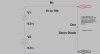
ZenerTest3.jpg

Use three 9v batteries, and you will get about 28vdc across the output. Connect the cap in place of the zener, with the plus side of the cap to the resistor. A 1kΩ resistor will charge up fast, and show a voltage drop across the resistor it the cap is leaking. A higher resistance will charge slower, but be more sensitive to the leakage current. A good cap will charge to the battery voltage (eventually) with no voltage drop across the resistor, if there is no leakage.
You will have to have the cap out of the circuit to test it with this jig. It can be used to test in-circuit on zeners and STV diodes (with unit power off).
This eliminates the need for a dc bench supply, and you can stack as many 9v batteries as you need to get enough voltage to test caps, as long as you do not exceed the rated voltage of the cap.
For testing higher voltage zener diodes you need to have a voltage higher than the zener voltage.

 
i often use the 200 ohm scale beep test to get go no go with caps . i catch most like that especially shorted or open ones .
 
Well, if this were 15 years ago I'd be waiting until at least Monday, but with Amazon all my replacement components will now be here today (after ordering yesterday). I've also purchased almost everything for my DBT and I'll be putting that together as well. I'll let you guys know when I'm ready for next testing steps.

I had already purchased most of it when I saw your post so here's what I have coming here today. I can go to somewhere overpriced but convenient today if any of this won't work.

1k ohm 1w resistors +-1% Metal Film Resistor | Qty 125
Nichicon KA capacitors 35V 220uf | Qty 4
qty 100 | 100ohm 1/4w resistor +-1% Metal Film Resistor | Qty 100
 
Last edited:
DBT is built and working. It's somewhere between ugly, and very ugly but tested and fully functional.

One more suspicious item I discovered (picture attached). This fuse (FU₄) looks burned but not severed. It's a 125v/4a and connects to the point labeled 34 (as opposed to FU₃ connected to 35). On the schematic (and physically) this fuse appears to be between the power pack and the switches/knobs on the front panel.
 

Attachments

  • IMG_20210801_142718.jpg
    IMG_20210801_142718.jpg
    70.2 KB · Views: 12
  • IMG_20210801_142658.jpg
    IMG_20210801_142658.jpg
    79 KB · Views: 12
Last edited:
Soldering is complete. It's not pretty but it's done. Enclosed are some pics. First time soldering except to remove the stuff earlier. Are these adequate?
 

Attachments

  • IMG_20210801_165426__01.jpg
    IMG_20210801_165426__01.jpg
    125.2 KB · Views: 16
  • IMG_20210801_165448__01.jpg
    IMG_20210801_165448__01.jpg
    128.7 KB · Views: 16
DBT is built and working. It's somewhere between ugly, and very ugly but tested and fully functional.

One more suspicious item I discovered (picture attached). This fuse (FU₄) looks burned but not severed. It's a 125v/4a and connects to the point labeled 34 (as opposed to FU₃ connected to 35). On the schematic (and physically) this fuse appears to be between the power pack and the switches/knobs on the front panel.
that's the right channel speaker fuse
 
FU4 (and FU3) are speaker protection fuses. The only way to be sure it is good is check it with an ohmmeter on the lowest range. Fuses have been known to look good but be bad. Or just replace it.
 
I did! They arrived with everything else. I'm about to start that now. FU3 actually measured the same resistance (.2 ohm) as the one that looked fine. I'll replace it tomorrow since it seems adequate for now in terms of performance.

The resistors are 1kohm 1w +-1%
How do I go about setting up this temporary STK pack replacement with resistors?

I read on a separate thread resistors between 1-3 and pins 8-0 on both sides?

If those are the pin numbers, do I solder the resistors or can I just pin them out to the correct slot?
 
Last edited:
Ok, so I went ahead and pinned the resistors into the slots where the STK pack would go in the pins I mentioned previously (0-8, 1-3 for both packs). Then I measured the resistance at the solder points between the same pins to ensure there was connection, and they measured at ~1k ohm mark. I'm going to wait for confirmation and instruction before proceeding from here.

Is it imperative to solder them to the board or is pinning them out adequate for testing? Not avoiding the effort, just not all that confident in soldering skills just yet
 
Last edited:
should be fine to power on dbt and measure dc volts at the speaker terminals . it should be close to zero volts .
 
should be fine to power on dbt and measure dc volts at the speaker terminals . it should be close to zero volts .

Ok. So, going to plug into DBT and power on momentarily.

To take voltage at the terminals do I ground to the chassis and then take reading at the terminal?
 
Ok powered up. bulb lit up pretty bright off the bat, then dimmed to barely visible. <1mV at each terminal .5-.7 ish. I did end up taking the reading just red to red black to black at the terminal.
 
Back
Top Bottom