• The move to the new server is done. There are some software and database maintenance updates in process. This has us passing the hat around to help out. We appreciate any donations. Seriously, even a dollar helps. The payment page may be found here - https://www.audiokarma.org/support.html

SX-880 with protection issues

is anyone making the pa3004 clones for those of us that cannot make them ourselves?

The PA3004 clone was intended to be a DIY project, neither of us that designed it wanted to 'go into business' selling them as complete, tested units.
If you want to build one and know how to solder, you can. You will need to order the parts yourself. If you make a donation to AK or become a Subscriber I will send you a bare through-hole PCB. I have a few. The original intention was to provide the info for people to order the boards from a PCB manufacturer, order their parts, and then build their own.
Link to all the info is here: PA3004 chip PCB substitute
 
I have recapped my sx-880 and I too am having protection relay dropout issues. I have been reading the threads so far and one thing that confuses me, is the suggestion in another thread to increase the heat sink resistor value and power rating. In addition, there was the belief that a 47uf cap is in backwards with regard to polarity. The suggested fix is to replace this cap with a 220uf, reversing the polarity of the original. The poster even said that the PCB was labeled incorrectly with regard to the polarity of this cap. I haven't heard from anyone else on these issues. Can someone confirm or deny whether these changes will solve the issue? Currently, (after recap), with 8 ohm speakers attached (1 set), the protection relay drops out when volume is increased to just under half volume. If left at this volume, the relay will trip out and reset about 20 seconds later. Of course it will continue to cycle unless the volume level is lowered.

I was concerned on first opening the unit, as I did see signs of overheating of a heat sinked transistor near the protection relay.
 
Actually, I've been having component numbering issues with this receiver. Also, I'm having the same issue on a recently rebuilt SX-980. Even though I recapped it as well as the SX-880, they are having the same issue. I tested the SX-980 this morning and it's tripping the same as the SX-880 protection relay. There has to be something in common with these two receivers that is causing the relay to trip open at almost half power on the volume controls. I believe the overheating transistor in the SX-880 is numbered D721. I'll check it again to make sure. What I really would like to know is if the 47uf cap located very close (physically) to the overheating transistor. In addition, the poster said that this overload/overheating issue can be solved by replacing this cap with a 220 uf and reversing the polarity. What I'm trying to find out is: Is this for real? If so, does it also apply to the SX-980? The poster also said that increasing the 5W resistor mounted on the main heat sink, be replaced/modified to be 440 ohms @ 10W. Can anyone tell me if this is true, and is it a fix for the overheating and tripping of the protection relay??

Until I ran into this problem with the SX-880, I hadn't noticed the SX-980 having the problem as well. I went out last night and found that if I increase the volume to almost half, with only one set of 8 ohm speakers operating, the 980 protection relay also opens and then closes back in. I didn't realize thhis since I had never turned the volume up that high on the 980. Back to the SX-880, I did pull the D721 transistor and tested it with my Peak DCA tester. It tested good with no leakage. I reinstalled it. Still trips.

Previously, I had rebuilt an SX-850 and an SX-950. Never had this problem. Obviously, it's something to do with the design of the XX80 series. Does anyone have a tried and proved fix for this problem that apparently exists in both receivers?

I would also like to know where people are getting their component numbers from. The service manual seems to show none of the numbers that others are referring to. I don't have the Pioneer component number for the transistor that is over-heating. I could use some help on that as well, since I don't want to put out the wrong part number on the forum.

Here is the post I have been referring to:

Hello Folks,
I don't post very much. I read a lot. So in an effort to contribute to the folks I've learned so much from, I'll do my part with this little tid-bit. Take it for what it's worth.

AK is running slow for me tonight so I don't know if I'm simply repeating well-known information. But I'll do it anyway.

Pioneer SX-880. It appears that many people have discovered there are some problems with the protection circuit. The first, most obvious problem is that Pioneer didn't do their homework in calculation the power dissipation on the transistor-regulator that runs the protection circuit IC. This poor transistor has to drop 50 volts down to 13 volts at several hundred milliamps. This causes that poor transistor to cook and eventually die, usually taking the PCB and a few other components with it. This is a design flaw so if you have an 880, you are well served to modify it now instead of waiting for it to fail. The mod is simple if you are knowledgeable with electronics.

To fix the power dissipation on that transistor, simply DOUBLE that big power resistor that is mounted on the heat sink. It's a 220 ohm 5 watt. Take another and bend the bracket to fit them both in place, and wire it in series so that you get 440 ohm at 10 watts. This lowers the voltage on that regulator transistor which will give it a little more life. Those of you following the schematic will note that those resistors also feed the relay. My testing showed the relay still worked fine with the lower voltage present.

Now, on to the second problem. I run a pair of vintage polks that are rated about 6 ohms nominal but drop to a little above 4 ohms DCR. The Stock 880 hated these speakers, as well as my JBL Jubals. Not necessarily due to the low DCR (the Jubals are much higher), but likely due to excessive inductive kick back current from the speakers back into the amp circuit. I could test the system with 4 ohm resistors all day and have no problems. But the speakers would cause the protection to trip annoyingly early.

So I did a little digging. Those of you who've studied this circuit see that the service manual calls out a Wheatstone bridge circuit that sits across the emitter resistors on the power amp. It turns on a transistor when it sees a load smaller than a prescribed value (note that it's rectified so it's only monitoring half the cycle, and it's only on one emitter vs. both the pos and neg circuit). I tried futzing with the Wheatstone values in an attempt to lower the speaker impedance detection. I lowered this to 25% of the stock value and still could not keep the circuit from tripping with the polks. It improved, but not good enough. There is something else at play here. So returned the Wheatstone values to the stock values and I looked deeper down the circuit. In monitoring the trip signal that feeds the protection IC, I could clearly see it jumping when I turned it up. Jumping a lot. The circuit is clearly too sensitive.

What I also found was that the C418 (or C2 in the circuit description in the service manual) was mounted BACKWARDS relative to the DC voltage applied to it. So I replaced that cap, and also bumped up the value form 47 to 220uf to decrease the hair-trigger from all the pulses it gets from the bridge. This was the fix. Now my 880 can drive the polks and the Jubals into clipping with out tripping. Yet, when I put a pair of polks on one channel (well below the rated load of the amp), the circuit trips at high volume, as it should.

In summary:
1) Increase the power resistor mounted to the heatsink from 220 5w to 440 10w. This will save the regulator.

2) Pull C418 (C2) and reinstall in the correct polarity a slightly larger cap - I used 220uF. I seem to recall that even the PCB had the cap labeled backwards so this was a design error from day one. Check the voltage on that cap before you pull it, label the pos and neg voltage, and reinstall the new cap in accordance with the DC volts you see (you need to push the amp into tripping to see the volts on that cap). I wish I could be more descriptive but it's been a few weeks since I did the fix and can't remember whether it was miss-stuffed or miss-labeled. But it was definitely backwards.

Anyway, my 880 is happy now. Hopefully you others who may be experiencing problems can make your 880 happy too.

PS: I will say that the next thing I will want to do is buy a set of modern beefy transistors to replace the stock power amp transistors. Modern ones can take much more current than those old ones, with higher HFE. So that too will go a long way towards idiot-proofing the 880 for years to come. Cheap insurance.
 
Last edited:
Changing the resistor you mention is done to reduce the temperature of the regulator transistor for the +13v supply. Increasing its resistance to a too high value will cause the regulator to stop regulating properly because it runs out of headroom. I would not go over 330Ω. It is not likely to be the fix for false triggering of the protection relay, for which there are many possibilities. The problem (on both amps) needs proper troubleshooting, not guesses. It may be a failure on the protection circuit, or on the power amp, or elsewhere. The protection on the SX-980 may be working perfectly and you are just over-driving the amp. The protection circuit will trip under overload, then click back in after the timer runs out, then trip again, if it is still. overloaded: normal activity, doing its ob properly.
Also, FWIW, testing transistors on a low voltage battery powered tester will not tell you if the transistor is good, it just tells you it failed under its test conditions. It may pass the tester and still fail in circuit under real world conditions. I don't reinstall transistors I pulled, I just replace them. They are cheap enough it is not worth the wear and tear on the transistor and pcb traces to reinstall and then maybe have to replace again later.
 
On the SX-880 big schematic the power resistor on the heatsink is labeled as R1, it is a series power dropping resistor on the collector of the +13.5v regulator transistor. That transistor is labeled as Q26, and is a 2SD712 (original).
 
Well guys,

I have an update. The reason I've had trouble with comp IDs is that I've had trouble reading the schematic print. Anyway, I went ahead and measured voltage across C418. I found the same thing as the original poster; the PCB is incorrect in it's markings of polarity. I pulled the the 47 uf and replace it with a 220 uf @ 35v. The unit is now working correctly. With a pair of 8 ohm speakers connected, I cranked up the power, (all the time feeling sorry for my speakers) and even at max volume (very very briefly), the protection relay hung in there. As it was, it would have tripped far before even reaching 1/2 volume.

Waiting for the 220 ohm 5W resistor to gang up with the other and lighten the load on the Q26. Thought you might find this helpful. I'm going to take a look at the SX-980 tomorrow. My suspicion is that the same problem may exist there..
 
I still consider myself a noob and I'm still learning. You are right about testing transistors. I do realize that with the tester it certainly does not test under load and may test fine, but really isn't. I usually do replace transistors, but I didn't know the correct replacement for it. I'm sure if I dig down in the forum I would be able to glean the correct transistor number to replace D712. I pursued the C418 issue because it sounded plausible that a cap could be in backwards from the factory since I have seen that before on other rebuild projects. I am also going to increase the R1 values as previously suggested . . . .when I get my Mouser order.

I did go back into the SX-980. It also has a D712 transistor on the power board, but I didn't see evidence of an overheating on it or any other heat-sinked transistors on that board. However, the unit is tripping the protection relay at approximately the 45% (almost 1/2 volume) position on the volume control. It had occurred to me that maybe it was functioning correctly to protect the speakers, as the previous poster suggested. It is a level far above normal listening level.

Is it normal to go into protection before you get to half volume? I also took a look at the caps on that board. There are actually two 47 uf caps on that board. Different than the 880, but it was getting late last night so I wrapped it up. Back on it today. I'm going to power it up with speakers and see what I get for readings (ie polarity). I'm appreciative for the help I get from this forum, but as I said, I'm still learning.
 
I still consider myself a noob and I'm still learning. You are right about testing transistors. I do realize that with the tester it certainly does not test under load and may test fine, but really isn't. I usually do replace transistors, but I didn't know the correct replacement for it. I'm sure if I dig down in the forum I would be able to glean the correct transistor number to replace D712. I pursued the C418 issue because it sounded plausible that a cap could be in backwards from the factory since I have seen that before on other rebuild projects. I am also going to increase the R1 values as previously suggested . . . .when I get my Mouser order.

I did go back into the SX-980. It also has a D712 transistor on the power board, but I didn't see evidence of an overheating on it or any other heat-sinked transistors on that board. However, the unit is tripping the protection relay at approximately the 45% (almost 1/2 volume) position on the volume control. It had occurred to me that maybe it was functioning correctly to protect the speakers, as the previous poster suggested. It is a level far above normal listening level.

Is it normal to go into protection before you get to half volume? I also took a look at the caps on that board. There are actually two 47 uf caps on that board. Different than the 880, but it was getting late last night so I wrapped it up. Back on it today. I'm going to power it up with speakers and see what I get for readings (ie polarity). I'm appreciative for the help I get from this forum, but as I said, I'm still learning.
i do not have these issues, i turned my volume to max volume without speakers as they arent needed to test for your issue, without issue. I did a full rebuild as you are in the process of doing. If you want, I will supply my components and post them, just list which and i'll get back to you.
 
According to the previous poster, it seems you need to have speakers powered up to get the readings I'm talking about. Here (again) is the applicable part of his post:

"Check the voltage on that cap before you pull it, label the pos and neg voltage, and reinstall the new cap in accordance with the DC volts you see (you need to push the amp into tripping to see the volts on that cap). I wish I could be more descriptive but it's been a few weeks since I did the fix and can't remember whether it was miss-stuffed or miss-labeled. But it was definitely backwards."

If this guidance is incorrect, please enlighten me. How can you drive it into tripping with no speaker load? If you can post your list of parts that would be great. I have already recapped this entire unit. The tripping is post rebuild. I was just wanting to find out the replacement transistor numbers for the transistors on the power protection board. Mouser part numbers would also be helpful, if you have them. I also want to say, that following the recap, the DC balance, Idle current, etc were all checked and adjusted into spec per the service manual (as I always do).

Thanks
 
Last edited:
According to the previous poster, it seems you need to have speakers powered up to get the readings I'm talking about. Here (again) is the applicable part of his post:

"Check the voltage on that cap before you pull it, label the pos and neg voltage, and reinstall the new cap in accordance with the DC volts you see (you need to push the amp into tripping to see the volts on that cap). I wish I could be more descriptive but it's been a few weeks since I did the fix and can't remember whether it was miss-stuffed or miss-labeled. But it was definitely backwards."

If this guidance is incorrect, please enlighten me. How can you drive it into tripping with no speaker load? If you can post your list of parts that would be great. I have already recapped this entire unit. The tripping is post rebuild. I was just wanting to find out the replacement transistor numbers for the transistors on the power protection board. Mouser part numbers would also be helpful, if you have them. I also want to say, that following the recap, the DC balance, Idle current, etc were all checked and adjusted into spec per the service manual (as I always do).

Thanks
i I would go with their recommendation on load testing.

Main Board:
Transistors (dont use Ebay)
Outputs:
2SB705:2SA1216
2SD745:2SC922

C418: Replace with 220uf 25v Bi-Polar (or 50v if that's all you have) as you already know, this is the source of most protection circuit trips.

1. Replace the 47uf 35v caps with 47uf 50v
2. 47uf 6.3v are replaced with 47uf 25v
3. 100uf 50v are replaced with the same value caps
4. Replace the other 100uf lower value caps with 100uf 25v
5. Replace the old orange caps with 4.7uf 50v
6. Replace the rest of the 4.7uf caps with 4.7uf 63v
7. Other low UF rated capacitors are replaced with Wima Bi-Polar (if you need the schematic # LMK)

Transistors Main Board:
They should all be ECB except for the metal backed. Those are BCE, refer to pictures if you have them.
All ECB Transistors have the Emitter on the far left side writing facing you. C middle, B Right.
Obviously its reversed for BCE. And the board is marked where the Emitter goes anyway.
Replace (4) C1775 & (2) C945 with KSC1845
Replace A904 & A850 with KSA1013 (these go in opposite of the 904's 850's assuming they are still stock)
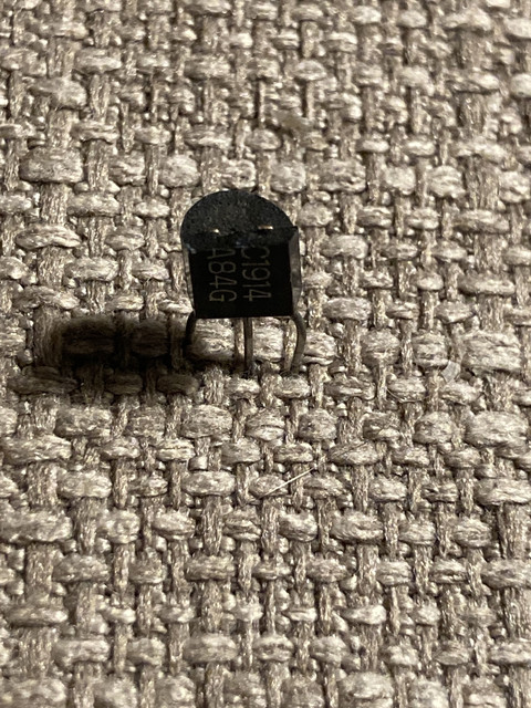
Replace C1914 with KSC2383 (verify pinouts)
Replace C1904's with KSC3503 (verify pinouts)
Replace C1384 & C1885 with KSC2690
Replace C1913 with KSC2073
Replace A913 with KSA940
Replace D712 with KSC2073
Replace B536 with KSA940
Replace D325 with KSC2073
Leave the KFETS alone
Replace your 4 large & small Diodes and verify their positions
Replace the Relay and make sure your extra pins are removed and not shorting anything
Verify your fuse resistors in the center with the heat resistant mesh arent drifting
Leave output transistors alone unless you want to reapply thermal grease

It doesnt sound like you need to do anything with the Tuner/Meter board but there are a few caps on that board

Replace your tuning board caps
Transistors A725/A726 are replaced with KSA992 (verify pinout, these are ECB to BCE I think)
I wouldnt mess with the filter caps if they are low ESR

Verify voltage is 0v. Attach a a single speaker volume at 0, in Aux. Ground to chassis, check voltage on Terminal 5 and adjust VR5 as needed. Cut the loop wire if you cant get close enough. Follow the same procedure on Terminal 12 and use VR6 to adjust.

Bias/Idle: Right Side- Attach Positive to term 8 Negative to term 10. Use VR7 to adjust 30mV. Left Side- Attach Positive term 14 Negative term 16. Use VR8 to adjust to 30mV


Look for leaking caps and blown-out transistors before you do any of this.

 
Hi Guys,

I'm back from a recon mission on the SX-980 protection issue. I have also reviewed a topic string titled
"Pioneer SX-980 goes into protection at 1/2 volume". So now I'm very confused, but I'll get through it.

I believe this protection board has been molested, (I called the Audiophile Protection Services (APS), but they have too many cases open to investigate mine)

Anyway, I wanted to see what transistors are actually installed on this board (AWR-156). Like I said, I'm a noob. I haven't had time to track down the exact comp IDs on the schematic. But here is what I have installed:

On AWR-156


Heat Sinked Transistors:

D712 (Mitsubishi mark) (original?)
B628 (NEC mark)
YL R210 CC631 (?)

Non-heat sinked (small) transistors:

2SA850 (Q3 ?) (original ?)
2SC945
2SC1735

Well, that's it. Two look like familiar numbers, the rest don't. But I'm thinking this may be a source of tripping the protection relay at less than 50% volume setting.

I've managed to put a list together to replace all of the transistors that are supposed to there. Before I order anything I want to resolve what's going on here. Ideas??

I also wanted some clarification on the statement made:
"C418: Replace with 220uf 25v Bi-Polar"

I did not see a Bi-polar cap there in the 880 or the 980. Maybe I screwed that up on the 980 because there's a polarized cap in there now ! I put it there because I saw no indication of it being a bi-polar. If I screwed up, please let me know.
 
Last edited:
@mgl99
Help us out and use the appropriate identifier for each component you are referring to, Q3, D4, R16, etc., otherwise we can only guess which component you are referring to.
Also the AWR-156 is an SX-980 pcb, this thread is about an SX-880.
I am confused by your post #113 . . .
 
Well, I started out in this thread and I didn't want to lose the folks trying to help me with the 880 and then the 980 with what appears to be a similar problem. If you can suggest what thread I should be posting under, please let me know. Yes, I'm going to go through the schematic and identify the comp IDs for these transistors.
I identified the board number to help clarify. I am aware that this is the pcb number. I provided the board number (AWR-156) to minimize confusion as to what board I was looking at. I guess I won't reference the board numbers in future if it's causing problems.

I guess I'll post back when: I figure out the comp IDs and when someone would kindly tell me where I should be posting this thread.

I really do appreciate all of the help. I have tried several times to help out forum members even though I'm a noob. I guess a lot of questions from noobies are annoying to senior more experienced members. I only hope that members will be understanding of this. I'm not trying to annoy anyone.

I will post more results as soon as I get them. I just think that different, possibly unsuitable, transistors may have been installed over the years on this board. I do appreciate the list of replacement parts you have provided. You did not use comp IDs for the components that you designated replacements for. In this case, you provided actual part numbers (not comp IDs) for the transistors I am concerned with. If the transistor numbers are different from what should be there, then I can only guess where the transistors you speak of are supposed to go.
 
Last edited:
Well, I started out in this thread and I didn't want to lose the folks trying to help me with the 880 and then the 980 with what appears to be a similar problem. If you can suggest what thread I should be posting under, please let me know. Yes, I'm going to go through the schematic and identify the comp IDs for these transistors.
I identified the board number to help clarify. I am aware that this is the pcb number. I provided the board number (AWR-156) to minimize confusion as to what board I was looking at. I guess I won't reference the board numbers in future if it's causing problems.

I guess I'll post back when: I figure out the comp IDs and when someone would kindly tell me where I should be posting this thread.

I really do appreciate all of the help. I have tried several times to help out forum members even though I'm a noob. I guess a lot of questions from noobies are annoying to senior more experienced members. I only hope that members will be understanding of this. I'm not trying to annoy anyone.

I will post more results as soon as I get them. I just think that different, possibly unsuitable, transistors may have been installed over the years on this board.
can you please tell me what you have replaced other than the capacitors on this sx-880? The thread is a little long now. Also, this issue persisted before & after replacing the capacitors, correct?
 
Okay, I'm back. Here's what I found.

Installed currently Replacement

(Q1) 2SD712 KSC2073

(Q2) 2SC1735 KSC2383

(Q3) 2SA850 KSA1013

(Q4) 2SB628 KSA940TU

(Q5) 2SR210 (?) KSC2073 (should be same as Q1)

(Q6) 2SC945 KSC1845


I have correct replacements for Q2, Q3, and Q6. All except Q5 appear to be original. I really don't know what it is that was put in it's place. It should be a 2SD712 and the same subsequent replacement as Q1 (KSC2073).

I'm going to put in an order for what I don't have, but whatever is installed in Q5, to me is unknown. I am going ahead and replace the ones I have replacements for and place and order for the ones I don't have. I am also going to replace Q8 on the main amp boards, when I figure out their values and replacements.

If I've got it wrong, please let me know. Thank you in advance.
 
To respond to Mark L. The problem with my SX-880 turned out to be the fact that C418, a 47uf @ 16V cap apparently was installed backwards from the factory. The protection board is also marked incorrectly as far as polarity is concerned for this cap. The original poster also stated that to alleviate further stress, it should be replaced with a 220 uf and in the correct polarity, which is basically opposite of the markings on the board. I verified what the poster said, and it made total sense to me, so I replaced C418 (which I had just replaced incorrectly, as it turns out, when I recapped the unit). I used a 220 uf @ 35v. I installed it opposite the polarity markings on the board. This stopped the premature protection relay tripping. The poster also recommended a change to R1 to take load off of the 13v power supply. However, in my unit, the only cause of the early tripping was the incorrectly installed C418. Here is what he said:

In summary:
1) Increase the power resistor mounted to the heatsink from 220 5w to 440 10w. This will save the regulator.

2) Pull C418 (C2) and reinstall in the correct polarity a slightly larger cap - I used 220uF. I seem to recall that even the PCB had the cap labeled backwards so this was a design error from day one. Check the voltage on that cap before you pull it, label the pos and neg voltage, and reinstall the new cap in accordance with the DC volts you see (you need to push the amp into tripping to see the volts on that cap). I wish I could be more descriptive but it's been a few weeks since I did the fix and can't remember whether it was miss-stuffed or miss-labeled. But it was definitely backwards.
 
Okay, I'm back. Here's what I found.

Installed currently Replacement

(Q1) 2SD712 KSC2073

(Q2) 2SC1735 KSC2383

(Q3) 2SA850 KSA1013

(Q4) 2SB628 KSA940TU

(Q5) 2SR210 (?) KSC2073 (should be same as Q1)

(Q6) 2SC945 KSC1845


I have correct replacements for Q2, Q3, and Q6. All except Q5 appear to be original. I really don't know what it is that was put in it's place. It should be a 2SD712 and the same subsequent replacement as Q1 (KSC2073).

I'm going to put in an order for what I don't have, but whatever is installed in Q5, to me is unknown. I am going ahead and replace the ones I have replacements for and place and order for the ones I don't have. I am also going to replace Q8 on the main amp boards, when I figure out their values and replacements.

If I've got it wrong, please let me know. Thank you in advance.

verify there are no blown transistors like I had. also there are multiple Q1's depending on the board, please specify which Q1 you're referring to or post a snippet of the schematic. with it listed.
IMG-0968.jpg
 
Last edited:
To respond to Mark L. The problem with my SX-880 turned out to be the fact that C418, a 47uf @ 16V cap apparently was installed backwards from the factory. The protection board is also marked incorrectly as far as polarity is concerned for this cap. The original poster also stated that to alleviate further stress, it should be replaced with a 220 uf and in the correct polarity, which is basically opposite of the markings on the board. I verified what the poster said, and it made total sense to me, so I replaced C418 (which I had just replaced incorrectly, as it turns out, when I recapped the unit). I used a 220 uf @ 35v. I installed it opposite the polarity markings on the board. This stopped the premature protection relay tripping. The poster also recommended a change to R1 to take load off of the 13v power supply. However, in my unit, the only cause of the early tripping was the incorrectly installed C418. Here is what he said:

In summary:
1) Increase the power resistor mounted to the heatsink from 220 5w to 440 10w. This will save the regulator.

2) Pull C418 (C2) and reinstall in the correct polarity a slightly larger cap - I used 220uF. I seem to recall that even the PCB had the cap labeled backwards so this was a design error from day one. Check the voltage on that cap before you pull it, label the pos and neg voltage, and reinstall the new cap in accordance with the DC volts you see (you need to push the amp into tripping to see the volts on that cap). I wish I could be more descriptive but it's been a few weeks since I did the fix and can't remember whether it was miss-stuffed or miss-labeled. But it was definitely backwards.

440 10w sounds way high. I wouldn't go over 330ohms 5w.

@merlynski covered this in one of my threads.
https://audiokarma.org/forums/index.php?threads/mounting-a-fan-inside-a-sx-880.983448/#post-15319222
get these values as I did and use a calculator
r1 measures 57.42v to terminal 7 & 38.35v to terminal 60

q26 13.57v/14.24v/38.67v
q35 pa3004 pin 1 13.57v

bias/idle
left side terminal 8/11 - 30.3mV
right side terminal 14/16 - 28.7mV

"OK, that means the resistor is dropping 19.7vdc.
19.7v ÷ 220Ω = 87mA, for a power dissipation of 1.65W
The transistor has 38.35v on the collector and 13.5v on the emitter for about 24.85v CE, and a power dissipation of 2.15W
Increasing the resistance to 270Ω will drop 23.4v, and 2W, leaving the transistor to waste 1.8W, and leave 37v on the collector.
Increasing the resistance to 300Ω will drop 26v, and 2.25W, leaving the transistor to waste 1.55W, and still leave about 18v of headroom.
If you use a 300Ω resistor and a bigger heatsink on Q26, I think it will run a lot cooler. A 5W resistor should be plenty robust enough to dissipate 2.25W"
 
Back
Top Bottom