

You are using an out of date browser. It may not display this or other websites correctly.
You should upgrade or use an alternative browser.
You should upgrade or use an alternative browser.
SX-880 with protection issues
- Thread starter dustmaker
- Start date
 !
! |
|
dustmaker
Active Member
I put it on a scope. It measures about 70 watts per channel. Smooth sign wave except occasionally the up slope becomes very jagged for about a second or maybe a little more than it smooths out again.
any idea what I am picking up? I noticed that if I move my hand in front of the unit, near to volume control, I can sometimes simulate this inconsistent wave. I am using a 1k sine wave from 5 volts down to 2 volts and getting similar results. The connection is alligator clips at the speaker terminal direct into oscilloscope (not using one of the probes).
any idea what I am picking up? I noticed that if I move my hand in front of the unit, near to volume control, I can sometimes simulate this inconsistent wave. I am using a 1k sine wave from 5 volts down to 2 volts and getting similar results. The connection is alligator clips at the speaker terminal direct into oscilloscope (not using one of the probes).

merlynski
Curmudgeon Electronicist
Are both channels doing it? That may indicate a power supply problem. Look at power supply rails to see if it showing up there. Have you replaced the power supply main/reservoir caps?
Look at the signal path with the other scope channel and see where it starts. If the jaggedness shows in the preamp section it will help narrow it down.
Make sure the front panel of the chassis has a good ground connection to the star ground point.
If you are driving it above its rated power capacity that may be the problem.
Can you post a picture?
Look at the signal path with the other scope channel and see where it starts. If the jaggedness shows in the preamp section it will help narrow it down.
Make sure the front panel of the chassis has a good ground connection to the star ground point.
If you are driving it above its rated power capacity that may be the problem.
Can you post a picture?
dustmaker
Active Member
Let me clarify. I ran the signal at 5 volts, then 4 volts, then three than two. Wanted to see if there was any difference. But except that the volume know was not turned up as high when I was at higher voltage, there really wasn’t any difference.By 5 volts down to 2 volts, do you mean the output level on the scope? What are you using for a load?
dustmaker
Active Member
I’ll retest it again tomorrow and take a picture of the wave form. I’ll follow your advice and try to narrow down the problem area.Are both channels doing it? That may indicate a power supply problem. Look at power supply rails to see if it showing up there. Have you replaced the power supply main/reservoir caps?
Look at the signal path with the other scope channel and see where it starts. If the jaggedness shows in the preamp section it will help narrow it down.
Make sure the front panel of the chassis has a good ground connection to the star ground point.
If you are driving it above its rated power capacity that may be the problem.
Can you post a picture?
also, I have DC volts on pin 7 of Q35. Can’t remember the exact number but I think I have around 4 vDC while also showing around 8 vAC on that pin. I’ll get the actual numbers and post them tomorrow
merlynski
Curmudgeon Electronicist
Once you are satisfied with the new PA3004 substitution board is working correctly in your SX-880, would you mind posting that in this thread please: PA3004 chip PCB substitute
We don't have an SX-880 confirmed there yet.
Thanks, merlyn
We don't have an SX-880 confirmed there yet.
Thanks, merlyn
merlynski
Curmudgeon Electronicist
Was that your input level or output level you are referring to at 5, 4, 3, and 2 volts?Let me clarify. I ran the signal at 5 volts, then 4 volts, then three than two. Wanted to see if there was any difference. But except that the volume know was not turned up as high when I was at higher voltage, there really wasn’t any difference.
dustmaker
Active Member
Output level from signal generatorWas that your input level or output level you are referring to at 5, 4, 3, and 2 volts?
merlynski
Curmudgeon Electronicist
If that is the Signal Generator output level going into the Aux input you are badly over driving the preamp stage. The Aux input for the SX-880 has an input sensitivity rating of 150mVRMS, which means that a 150mV signal is large enough for the preamp stage to drive the power amp output to its maximum rated power output level by adjusting the Volume control to its maximum position. A modern CD player may drive an input to as much as 2v. That will be quite a bit louder, for the same volume control setting, as a vintage CD player or tape player output.
FWIW a 150mVRMS sine wave will be 0.42v peak to peak on the scope.
Set your signal generator for its output to be 150mVRMS, then turn up the Volume control to see what level it can reach. Then see if still have that ragged output.
EDIT: correct math error
FWIW a 150mVRMS sine wave will be 0.42v peak to peak on the scope.
Set your signal generator for its output to be 150mVRMS, then turn up the Volume control to see what level it can reach. Then see if still have that ragged output.
EDIT: correct math error
Last edited:
dustmaker
Active Member
Thank you. Hopefully I didn’t damage anythingIf that is the Signal Generator output level going into the Aux input you are badly over driving the preamp stage. The Aux input for the SX-880 has an input sensitivity rating of 150mVRMS, which means that a 150mV signal is large enough for the preamp stage to drive the power amp output to its maximum rated power output level by adjusting the Volume control to its maximum position. A modern CD player may drive an input to as much as 2v. That will be quite a bit louder, for the same volume control setting, as a vintage CD player or tape player output.
FWIW a 150mVRMS sine wave will be 2.8v peak to peak on the scope.
Set your signal generator for its output to be 150mVRMS, then turn up the Volume control to see what level it can reach. Then see if still have that ragged output.
yes, turning down the signal input has fixed much of the distortion. I also, reset the dc offset and the bias to spec. I also tweaked the power meter monitors by about a 1/16th turn. Everything “looks” good except one channel has less amplitude on the sine wave for the same setting, pic attached.
I played the FM and it sounds clean and loud (or at least as loud as I can turn it up). I was able to measure output voltage and I WAS getting a consistant 23.9 volts AC output per channel before clipping, equating to about 70 watts per channel. Then I didn’t. Now I’m only measuring around 8 vAC. I first noticed when looking at the distortion on the sine wave and realized I had the volume knob turned up all the way and there wasn’t any distortion.
something happened and it’s affecting both channels. I tried a different multimeter and am getting the same results. I keep thinking it is something I’m doing, bad connection, incorrect setting, etc but I’ve checked everything several times and am still seeing low voltage. One thing I did notice was the dmm would go up to say 16volts for a fraction of a second than drop down to say 6 volts.
Any suggestions?
Attachments

merlynski
Curmudgeon Electronicist
I am assuming you are using the Aux input. Are you feeding both left and right channels from the same source? Like a Y connection so both are truly identical?
On your scope the two channels are 180° out of phase, which makes me think you do not have the channels tied together at the input, or one of the scope channels are inverted.
Does your Signal Generator have a meter that measures output level?
On your scope the two channels are 180° out of phase, which makes me think you do not have the channels tied together at the input, or one of the scope channels are inverted.
Does your Signal Generator have a meter that measures output level?
dustmaker
Active Member
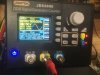
Attached is pic of my signal generator for future referenceI am assuming you are using the Aux input. Are you feeding both left and right channels from the same source? Like a Y connection so both are truly identical?
On your scope the two channels are 180° out of phase, which makes me think you do not have the channels tied together at the input, or one of the scope channels are inverted.
Does your Signal Generator have a meter that measures output level?
I never thought of a “Y” connection. Thank you. I put one in and the sine wave is now almost identical. So, it appears to be working correctly. I’m going to play with this for a day or two and see if I have any other issues. There are still some smaller value caps on the pcb that I’m going to change out and then it will be deemed a full recap of the main board.
Attachments
merlynski
Curmudgeon Electronicist
You are welcome! The Y connection eliminates differences between the generator's output impedance and the channels input impedances, and differing calibration of the generator's 2 output channel levels.
I spent many years working as a bench tech doing QA test and alignment of electronics. The tools being used are as much a part of the testing process as the Unit Under Test. So is the Tech!
I spent many years working as a bench tech doing QA test and alignment of electronics. The tools being used are as much a part of the testing process as the Unit Under Test. So is the Tech!
Last edited:
dustmaker
Active Member
I’m back near the beginning. It works, but if I turn the volume pot beyond half way the lights start to flicker and the relay clicks off. Volume knob goes further with left channel than right, but I also measure lower voltage on left channel. I’m measuring less than 8 volts per channel at max volume. So, my preliminary assessment is two issues. 1). Inadequate power; 2). Protection circuit ( I’ll check Q36, Q37, Q35)
dustmaker
Active Member
Both - After I do anything, I test it on the DBT than plug it in live if ok. When on DBT, I only get about 3-4 volts through speaker terminals but almost 8 volts when live. This is a third of what I had a few days ago.Are you using the DBT? That is counterproductive when trying to make music.
dustmaker
Active Member
Now I’m back to square 1. I turned the unit on to check voltages. Initially everything seemed to be ok, then it appeared that Q37 is bad again. I don’t recall the voltages, but B and E were about the same. I also noticed pin 7 on Q35 which should be measuring. AC voltage is also measuring about 3.6 vdc. After checking numerous other voltages I realized the one channel (right?) is no longer working. I didn’t do anything except check voltages. After puzzling this for a while I looked and noticed that the Zener diode, D28, is a modification. See pic. Could this be a source of my problems? All voltages were OK before, so I suspect something went bad while testing.Off DBT. Is your input set to Aux, with a 1kHz sine wave at 150mVRMS? You will have to turn the volume control way up to get near maximum output power. If so recheck your DC power supply voltages.
Attachments

merlynski
Curmudgeon Electronicist
D28 should be a single 14v zener, on the power supply board. Sometimes you can add another diode in series with a zener to increase the voltage, but it must be forward biased. Those don't look like they are connected that way. Sometimes you can use two lower voltage zeners to make a higher voltage. What is the dc voltage on the plus side of C410, sb +14vdc. That should be the same point as the cathode of D28.
Last edited: