

You are using an out of date browser. It may not display this or other websites correctly.
You should upgrade or use an alternative browser.
You should upgrade or use an alternative browser.
SX-880 with protection issues
- Thread starter dustmaker
- Start date

dustmaker
Active Member
If you are getting a quote from a fabricator, let me know the quantity for a price break and the cost per board. Depending on the cost, I may buy a bunch of themI may be getting some boards, let's see how that works out . . .
dustmaker
Active Member
The problems you are running into are why a pro at circuit board layout (not me) made the circuit boards' layout.
Your description seems correct. There are interactive logic functions in this device. And a re-settable timer. The power pin 1 is also an input. They are not readily apparent until you study it in depth. I spent hours studying Pioneer discrete protection circuits, and the logic in them and the PA3004 to come up with the circuit design. Then Alex bread-boarded it, and used his prototyping device and skills to make a final board design. You may find it easier to just acquire a bare board and build it that way. I do not know if he has any left, you could ask him. The information is all there to order more of them if you want/need to, from the same source he used. I put in a request for a quote from a US based PC maker, I have not heard back from them.
EDIT: The only pins that are not 'multi-function/inputs' are ground (5), and the output (3).
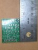
OK - I was fortunate to get a board from Merlynski for a replacement of the PA 3004. See the pics. First impressions:
1) This is a very well designed pcb. Much smaller that I anticipated. It is just slightly larger than the original chip in width and although over three times the height of the original, it isn’t an issue. I didn’t think all those components would fit on a board that size but they do.
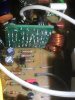
2). The pcb “snugly” fits in the allotted space eventhough the 880 doesn’t provide much space.
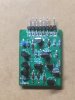
3). I may have built out the pcb backwards. While some pcb’s have sketched components on the foil side and others have it on the component side, I wasn’t thinking and treated the board ‘as if’ the sketch was on the component side. Is it?
4). All components are well documented which makes it easy to build.
the first pic shows the size of the pcb. The second pic shows completed pcb and the third pic shows the board installed. Pin 1 is on the right
Attachments
Last edited:
dustmaker
Active Member
I’m confused (as usual). In the pic above, did I build the pcb correctly? If so, either I did something wrong or I have something else going on in this receiver. When I first replaced Q26, it blew out the PA3004. I replaced Q26 again and it went bad again. I have a new ksc1845 in place and it still seems to be working, but I haven’t taken the unit off the DBT and the relay will not engage
Last edited:

merlynski
Curmudgeon Electronicist
Silkscreened PCB components labels are typically printed on the component side. This convention probably arose from hand stuffing boards during manufacturing, so the correct component went in the right place, with the correct orientation.I wasn’t thinking and treated the board ‘as if’ the sketch was on the component side. Is it?
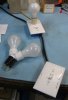
Some units don't pull in the relay easily on the DBT. Does it pass the DBT test? (bulb flashes bright when power is first turned on, then goes dim). What wattage bulb are you using? If you put a higher wattage bulb in your DBT it still provides some protection, while allowing power supply voltages to rise up more.
I use a single 60W or two 60W (for 120W).
My DBT setup:
Once the unit passes the DBT test, it (almost) always is safe to go to full mains voltage.
You will need to be on full mains to properly troubleshoot Protection problems, after the unit passes the DBT test.
SX-1050 on DBT, 120W (with two 60W) bulbs:

My Protection relay pulled in quite slowly on the 60W bulb, faster on 120W. Only got an authoritative click on full mains. Soft Start relay was similarly slow.
dustmaker
Active Member
Well, my DBT is 100 watt, unless I know I have some serious issue, in which case I use a 60 watt.
i double checked and the 100 watt would glow them dim, so I switched to live. Nothing happened. I then read the voltages on the q36 and it would appear that transistor is now blown. I then checked the new pcb pins and I thin that is also blown. I need to check the circuit as it would appear something is causing the Q36 to short and destroying the Q37
edit: I should have said Q35 and not Q37. Q35 is the PA3004, not q37. My apologies for the mix up. By incorrectly mentioning Q35, I’m adding confusion to the discussion.
Q36 is the transistor mentioned early in this thread that MTF said to pull out to see if the unit would play. When I put a new Q36 in, it blew out the Q35 (PA3004).
i double checked and the 100 watt would glow them dim, so I switched to live. Nothing happened. I then read the voltages on the q36 and it would appear that transistor is now blown. I then checked the new pcb pins and I thin that is also blown. I need to check the circuit as it would appear something is causing the Q36 to short and destroying the Q37
edit: I should have said Q35 and not Q37. Q35 is the PA3004, not q37. My apologies for the mix up. By incorrectly mentioning Q35, I’m adding confusion to the discussion.
Q36 is the transistor mentioned early in this thread that MTF said to pull out to see if the unit would play. When I put a new Q36 in, it blew out the Q35 (PA3004).
Last edited:
merlynski
Curmudgeon Electronicist
Q36 does not have a direct connection to Q37 that I can see on my schematic.
Verify the orientation of D35, and that it is not shorted OR open.
If D35 is shorted (or backwards) it will kill Q37 instantly when the PA3004 tries to pull in the relay by turning on Q37.
If D35 is open the inductive kick-back from the relay could easily kill Q37 when the PA3004 tries to shut off Q37.
Pull Q36 and Q37, don't replace them yet, and let's look at voltage on the board with them out.
Verify that the + side of C407 is about +56.4vdc.
If the PA3004 is happy pin 3 should go positive to about +13vdc or so . . .
Verify that pin 1 on the PA3004 is +13vdc.
Measure DCV where the collector of Q37 should be, it will rise to about +56vdc.
While Q36 is out measure DCV on pin 4 of the PA3004.
EDITED
Verify the orientation of D35, and that it is not shorted OR open.
If D35 is shorted (or backwards) it will kill Q37 instantly when the PA3004 tries to pull in the relay by turning on Q37.
If D35 is open the inductive kick-back from the relay could easily kill Q37 when the PA3004 tries to shut off Q37.
Pull Q36 and Q37, don't replace them yet, and let's look at voltage on the board with them out.
Verify that the + side of C407 is about +56.4vdc.
If the PA3004 is happy pin 3 should go positive to about +13vdc or so . . .
Verify that pin 1 on the PA3004 is +13vdc.
Measure DCV where the collector of Q37 should be, it will rise to about +56vdc.
While Q36 is out measure DCV on pin 4 of the PA3004.
EDITED
Last edited:
dustmaker
Active Member
I pulled Q36 and Q37. Out of circuit, Q36 seems to be OK but Q37 is shorted and functioning as a resistor. B to E is 22.5Ω. Q37 is a KSC2690.
. D35 was shorted and measuring as a 22Ω resistorQ36 does not have a direct connection to Q37 that I can see on my schematic.
Verify the orientation of D35, and that it is not shorted OR open.
If D35 is shorted (or backwards) it will kill Q37 instantly when the PA3004 tries to pull in the relay by turning on Q37.
If D35 is open the inductive kick-back from the relay could easily kill Q37 when the PA3004 tries to shut off Q37.
Pull Q36 and Q37, don't replace them yet, and let's look at voltage on the board with them out.
Verify that the + side of C407 is about +56.4vdc.. I pulled D35, Q36, Q37. +C407 is 55.5vdc
. Pin3 is measuring 163mvdcIf the PA3004 is happy pin 3 should go positive to about +13vdc or so . .
Pin1 13.1Verify that pin 1 on the PA3004 is +13vdc.
55.5Measure DCV where the collector of Q37 should be, it will rise to about +56vdc.
4mvdcWhile Q36 is out measure DCV on pin 4 of the PA3004.
EDITED
merlynski
Curmudgeon Electronicist
KSC2690 is the correct/good replacement for Q37
UF4004 is a 1A, 400V fast recovery diode, IMO you don't need a fast recovery diode in that application. 1N4004 is a common 1A 400V diode, 1N4007 or similar would be OK. Almost any rectifier with a PIV over 100vdc will probably work. The highest reverse voltage it ever sees is the DCV across the relay coil when it is pulled in. The forward current is limited by the resistance of the coil itself when it releases. I have seen people use a 1N4148 signal diode. That would work as a temporary replacement, IMO, anyway.
UF4004 is a 1A, 400V fast recovery diode, IMO you don't need a fast recovery diode in that application. 1N4004 is a common 1A 400V diode, 1N4007 or similar would be OK. Almost any rectifier with a PIV over 100vdc will probably work. The highest reverse voltage it ever sees is the DCV across the relay coil when it is pulled in. The forward current is limited by the resistance of the coil itself when it releases. I have seen people use a 1N4148 signal diode. That would work as a temporary replacement, IMO, anyway.
dustmaker
Active Member
Good - I have a 1N4004. I was hoping that you would say it would work.KSC2690 is the correct/good replacement for Q37
UF4004 is a 1A, 400V fast recovery diode, IMO you don't need a fast recovery diode in that application. 1N4004 is a common 1A 400V diode, 1N4007 or similar would be OK. Almost any rectifier with a PIV over 100vdc will probably work. The highest reverse voltage it ever sees is the DCV across the relay coil when it is pulled in. The forward current is limited by the resistance of the coil itself when it releases. I have seen people use a 1N4148 signal diode. That would work as a temporary replacement, IMO, anyway.
dustmaker
Active Member
I’m finally getting back to this unit. I had to rebuild the PA3004 board because it died when I connected it it due at least partially to the diode mentioned above. I still have Q36 and Q37 out. Where Q35 pin 7 would go is measuring about 20vAC. How do I go about testing this unit before I put the Q35 back in?
merlynski
Curmudgeon Electronicist
That AC voltage there does not surprise me, as it comes from a power supply winding that drives a bridge rectifier for ≈±55vdc supplies. It has a 1MΩ resistor between that pin and the winding, (as well as one to ground) so it will be very low current. Your actual measurement there (without the PA3004 in place) is affected by the voltage divider ratio of the 1MΩ series resistor from the winding, and the 1MΩ resistor to ground paralleled by your meters input impedance (likely ≈1MΩ) to ground.I’m finally getting back to this unit. I had to rebuild the PA3004 board because it died when I connected it it due at least partially to the diode mentioned above. I still have Q36 and Q37 out. Where Q35 pin 7 would go is measuring about 20vAC. How do I go about testing this unit before I put the Q35 back in?
The things I would look at is DC power supply voltages, including the relay supply, the DC offset at the power amp outputs before the relay (amp pins 65 & 68) and check the bias settings.
NO speakers should be connected for these next two tests. You can test the relay circuit without installing Q37 by grounding the pad where the collector would be, that will pull in the relay. Note that IF the relay diode is backwards or there is something parallel to the relay coil shorting it out you may smoke something else (like R421). If you put Q37 back in place you could simulate the PA3004 pull-up to the base of Q37 by touching a 100kΩ resistor from Q35 pin 3 to pin 1. That should pull in the relay, if the rest of the relay circuit is good. If you fry another Q37 you will need to look deeper into why that is happening.
dustmaker
Active Member
Damn. I checked and still screwed up. I have Q37 in, but I left out Q35. So it is Q35 and Q36 that are out of circuit. I want to leave Q35 out until I’m sure everything else is working. When I redid the Q35 board I had a lot of trouble unsoldering components so want everything to be correct before reinstalling so I don’t have to do it againThat AC voltage there does not surprise me, as it comes from a power supply winding that drives a bridge rectifier for ≈±55vdc supplies. It has a 1MΩ resistor between that pin and the winding, (as well as one to ground) so it will be very low current. Your actual measurement there (without the PA3004 in place) is affected by the voltage divider ratio of the 1MΩ series resistor from the winding, and the 1MΩ resistor to ground paralleled by your meters input impedance (likely ≈1MΩ) to ground.
The things I would look at is DC power supply voltages, including the relay supply, the DC offset at the power amp outputs before the relay (amp pins 65 & 68) and check the bias settings.
NO speakers should be connected for these next two tests. You can test the relay circuit without installing Q37 by grounding the pad where the collector would be, that will pull in the relay. Note that IF the relay diode is backwards or there is something parallel to the relay coil shorting it out you may smoke something else (like R421). If you put Q37 back in place you could simulate the PA3004 pull-up to the base of Q37 by touching a 100kΩ resistor from Q35 pin 3 to pin 1. That should pull in the relay, if the rest of the relay circuit is good. If you fry another Q37 you will need to look deeper into why that is happening.
merlynski
Curmudgeon Electronicist
Further testing with Q35 out is fine.
Having Q36 out will not hurt the testing with Q35 out, but it does eliminate the overload detection. You can do both those tests I described, above, with Q37 in place. Ground the collector of Q37 first, if the relay pulls in and no problem occurs, testing the pull-up on the base will verify Q37 is good. Q35 does not need to be installed to test the pull up. If Q35 (PA3004) is installed, and there is a fault condition, Q35 will clamp the base to 0vdc (pin 3) and the 'pull up with a resistor' test will not work to pull in the relay.
You can put a new Q36 back in and measure DCV on pin 4. If there is no fault in the overload circuit, pin 4 should be about 0vdc. If it is not 0vdc post the voltage and we will look at it further.
Having Q36 out will not hurt the testing with Q35 out, but it does eliminate the overload detection. You can do both those tests I described, above, with Q37 in place. Ground the collector of Q37 first, if the relay pulls in and no problem occurs, testing the pull-up on the base will verify Q37 is good. Q35 does not need to be installed to test the pull up. If Q35 (PA3004) is installed, and there is a fault condition, Q35 will clamp the base to 0vdc (pin 3) and the 'pull up with a resistor' test will not work to pull in the relay.
You can put a new Q36 back in and measure DCV on pin 4. If there is no fault in the overload circuit, pin 4 should be about 0vdc. If it is not 0vdc post the voltage and we will look at it further.
dustmaker
Active Member
Using 100watt DBT; Q35 out; Q36 outFurther testing with Q35 out is fine.
Having Q36 out will not hurt the testing with Q35 out, but it does eliminate the overload detection. You can do both those tests I described, above, with Q37 in place. Ground the collector of Q37 first, if the relay pulls in and no problem occurs, testing the pull-up on the base will verify Q37 is good. Q35 does not need to be installed to test the pull up. If Q35 (PA3004) is installed, and there is a fault condition, Q35 will clamp the base to 0vdc (pin 3) and the 'pull up with a resistor' test will not work to pull in the relay.
You can put a new Q36 back in and measure DCV on pin 4. If there is no fault in the overload circuit, pin 4 should be about 0vdc. If it is not 0vdc post the voltage and we will look at it further.
Q37 collector to ground - relay pulls in
Q35 100k resistor pin 1 to pin 3 - relay pulls in
I will put Q36 in and check DCV on pin 4

dustmaker
Active Member
IT WORKS. Your board for the PA3004 definitely works in place of the original chip.
I still need to check voltages and let it run for a while, check dc offset and bias voltages. It does play music (FM) at low volume into both 8 ohm and 4 ohm speakers. The only thing that seems a little funny is when I turn the unit off, the relay disengaging seems to be just a little too loud. Might just be me though.
I still need to check voltages and let it run for a while, check dc offset and bias voltages. It does play music (FM) at low volume into both 8 ohm and 4 ohm speakers. The only thing that seems a little funny is when I turn the unit off, the relay disengaging seems to be just a little too loud. Might just be me though.