• The move to the new server is done. There are some software and database maintenance updates in process. This has us passing the hat around to help out. We appreciate any donations. Seriously, even a dollar helps. The payment page may be found here - https://www.audiokarma.org/support.html

SX-939 worth the effort?

Electrolytics, YES. Ceramics, NO! You can lift one leg of each diode and test. If they test ok, you can leave them in. If not, 1n4006 and 1n5406 are good replacements. UF4006 and UF5406 are faster, & quieter with reference to Switching noise. I can't hear any difference between those and 1n4006 and 1n5406 but your hearing may be better than mine.
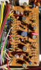
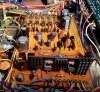
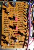
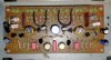
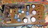
I completed my SX-939 project. It is not a full restoration project though. I recapped power supply, protection, phono, and control amplifier boards. Lots of help from Larry made my first project ends with satisfactory results. Now I can clearly hear the sonic differences before and after.
Thanks a lot, Larry. It was great fun! Here are some pics.
 

Attachments

  • Control amplifier.jpg
    Control amplifier.jpg
    118.8 KB · Views: 34
  • Phono board.jpg
    Phono board.jpg
    66.7 KB · Views: 33
  • power supply.jpg
    power supply.jpg
    113.1 KB · Views: 35
  • Protection board.jpg
    Protection board.jpg
    76.8 KB · Views: 36
Next Winter,you can finish it. Good job so far. One thing YOU SHOULD DO, it put a 1n4004 DIODE across pins 9 & 10 on the protection circuit. Cathode (striped) side to pin 10. It will protect (EDIT) Q6 from back voltage when the magnetic field collapses in the relay on shutdown.
 
Last edited:
BRAIN FART ALERT! Q6 is the transistor not Q7. I edited Post 42 to reflect.
Larry: I am starting on my SX-1010 soon (Big job!). I will do a complete restoration of it. After that I will go back to 939 and finish it and will follow your all suggestions.
 
Note that some (a lot of) the boards on the 1010 are same as the 939. Compare the board #'s between the Service manuals. On those boards do the same as you did on the 939 using pretty much the same parts. There may be 1 or 2 substitutions from the 939 to the 1010. So be aware of that. The 1010 has 2 amp boards vs. 1 in the 939. Also it has shielding boxes around the tuner. The power supply is a bit more involved.
 
And do note that the bias settings in the SX-1010 Service Manual have been determined to be incorrect, 25mV is my memory on tne correct setting.
 
Note that some (a lot of) the boards on the 1010 are same as the 939. Compare the board #'s between the Service manuals. On those boards do the same as you did on the 939 using pretty much the same parts. There may be 1 or 2 substitutions from the 939 to the 1010. So be aware of that. The 1010 has 2 amp boards vs. 1 in the 939. Also it has shielding boxes around the tuner. The power supply is a bit more involved.
Thank you Larry. I will update on it.
 
When I was desoldering the transistors in sx-1010 protection board last night, half of one eyelet in one hole detaches (it happened to one hole out of around 20 holes I desoldered last night). It was very hard to put solder on that side of the hole with the new transistor leg. Is there anyway to fix it? use of liquid flux or conductive pen will be of any help?
Thanks
 
De-solder the old transistor, replace with a new one, and after scraping the trace clean, bend over the leg onto the trace and solder the length of the leg to the trace.

To back up Jeff's quote on the Bias, Pioneer engineers goofed on the same math on the 1010 as on the 939. It's 25mv, not 50mv.
 
De-solder the old transistor, replace with a new one, and after scraping the trace clean, bend over the leg onto the trace and solder the length of the leg to the trace.

To back up Jeff's quote on the Bias, Pioneer engineers goofed on the same math on the1010 as on the 939. It's 25mv, not 50mv.
Larry thanks!
 
I was trying to replace SX-1010 power supply board diodes 1S1885 (there are 3) by 1N5404, I found the leg of 1N5404 is too thick to go in the hole. Can I use same 1N4004 which I am using to replace SIB01-4 (there are 4)?
Thanks
 
Looking into the specs of 1S1885 (100V, 1A) and IN4004 (400V, 1A) I think they are interchangeable. Am I missing something else here?
Thanks
 
1n4004 is fine for the 1s1885.
Larry: As of now, I have finished the power supply board, protection board, control amplifier and equalizer amp. In PS board I have replaced all the capacitors, all the transistors (except 3 heat sink transistor as I will get those latter this week), all the regular didoes except zener ones. In the protection board I have replaced all the capacitors and transistors. In equalizer and control amplifier all the capacitors and transistors are replaced. I have measured the voltages at different pins in PS and protection board and they are little different from the manual. Below is the list the values given in manual are in parentheses.

Power Supply

Pin 8 = 13.1 VDC (13.4)
Pin 9 = - 12.7 VDC( -13)
Pin 10 = -56.3 VDC (-56)
Pin 13 = 34.6 VDC (35)
Pin 14 = 55.6 VDC (56)
Pin 15 = 25.2 VDC (24)

Protection Board

Pin 2 = -12.9 VDC (-13)
Pin 9 = 8.1 VDC (no value given in manual)
Pin 10 = 33.2 VDC
Pin 11 = 33.2 VDC (35)
Pin 12 = 7.9 VAC (7.5)

Are these values look reasonable? Receiver is running fine.
Thanks
 
Voltages are fine. The schematic values are based on a line voltage (Wall) of 120VAC. If your's (Wall voltage) is different expect a slight difference. But no more than or less than 5%.
 
Voltages are fine. The schematic values are based on a line voltage (Wall) of 120VAC. If your's (Wall voltage) is different expect a slight difference. But no more than or less than 5%.
Larry thanks and I will update as I progress. To be honest I am a little scared about the power amp section regarding access. Do you think can I flip the heat sink over the board without disconnecting any wires and power transistors?
 
Back
Top Bottom