INTRODUCTION
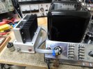
The McIntosh Unity Coupled output stage — as typified by the McIntosh MC 240 — is recognized world wide as the pentacle of achievement in pentode amplifier design, producing at once the most power, least distortion, and highest efficiency of all pentode arrangements. These combined qualities simply cannot be matched by any other practical pentode configuration. I have a very nice example of the last version of this amplifier, and recently had it on the bench for a checkup.
After basic component and voltage checks, these amplifiers are often given their final health exam in the classic Mac Clinic style: THD and power response are checked over the entire audio band at rated power output with both channels driven. If these results are typical and within Mac’s guaranteed specifications, then invariably all is deemed to be good.
A couple of small signal tubes were replaced, and then my own unit met Mac’s distortion specs right up to maximum power output at a very healthy 56 watts per channel with both channels driven — the extra margin of power output developed being one of the most recognized but unspecified characteristics of McIntosh amplifiers.
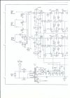
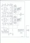
With this checkup however I did further testing, which uncovered some other performance opportunities worth pursuing. A discussion of them follows, along with an explanation of the measures available for resolve. For those wishing to follow along, a copy of the final schematic is provided at the end, with all component references made relative to it.
INFRASONIC TRANSIENT STABILITY
Transient triggering of the amplifier produced less than desirable stabilization after a transient signal was injected. On a scope, this could be seen in the form of decaying oscillations of the base line for about 2 cycles before settling again. The amplitude of the trailing oscillations are in direct proportion to the amplitude of the transient signal applied. At high power levels, such instability can be hard on the tubes, steals power, and is obviously not an original component of the transient applied.
This conduct was traced to the combination of using a significant amount of NFB (21.5 db) within in the global feedback loop, coupled with the presence of four LF poles occurring within the loop as well. Without careful design attention, such a configuration can become unstable rather quickly at low frequencies.
Mac did a good job of stabilizing its design by adding partial direct coupling between the phase inverter and driver stages (via R19,20,42,43), to effectively eliminate one of the LF poles. With a slight re-configuration as to how the NFB is reinserted into the input stage, an additional LF pole can effectively be eliminated as well, which then further stabilizes the loop to produce the rapid settling desired.
This can be accomplished as follows:
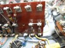
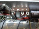
1. Disconnect the leads from the NFB networks (R11,C2 & R34,C12) at their existing terminals on the main tag board, and reconnect them to the tag board terminals directly above them connected to pins 3&8 of V1 respectively.
2. Remove R12 and R35.
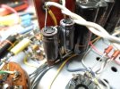
3. Change C3 and C13 to 2200 uF @ 6 vdc caps.
The effect of this change is to prevent the feedback signal from passing through C3 and C13, while still maintaining the original gain of the AF Amplifier stage V1, and providing the same amount of NFB as originally applied. The input sensitivity of the amplifier is unchanged as a result of this modification, but it does produce a very slight (and insignificant) reduction in both plate and cathode voltages in both sections of V1 (~ 5 volts and 0.1 volts respectively).
COMMENT: As originally designed, the 240 could hardly be considered “unstable” by any means. But with a greater understanding as to how stability impacts sound quality, and the availability of component values in smaller packages today, it makes for a practical modification that can achieve even better LF stability than before.
HIGH POWER TRANSIENT DISTORTION
Applying a full power audio sine wave transient signal to both channels from a quiescent state displayed serious initial clipping, before quickly rising to an undistorted full power waveform. This “blocking” distortion could only be eliminated by backing the transient power burst down to 39 watts per channel. Mac never provided a specification for undistorted transient power, but if the amplifier could not reach a transient power of at least rated power output without the blocking distortion occurring, then it would seem that something was not quite right.
It was also noted that:
1. When the blocking distortion occurred, the two channels recovered at different rates.
2. If the transient was applied in rapid fire succession, the clipping only occurred on the first transient — not succeeding ones. But wait a few moments, and this conduct would repeat itself again.
3. If only one channel (either one) was fed the transient, the blocking distortion did not occur.
The conclusion drawn then is that when instantaneous power is required in both channels that approaches rated power output (think Telarc 1812 cannon shots for example), all that extra undistorted steady state power that the 240 is capable of producing becomes questionable as to whether it really translates into any useful headroom under such demanding dynamic conditions. This is not meant to criticize the 240’s design, but does suggest that the long understood extra headroom provided may need to be looked at in a new light. That begins with understanding why the amplifier’s capable power output is so much greater than rated power output to begin with.
Mac has always championed conservative ratings, but in this case, the answer goes back to a decision Mac made dating back to the release of the original MC 30 amplifier. Before that time, Mac’s original Unity Coupled 6L6 amplifier — the 50W-1 — was their mainstay product (not counting the short lived A-116). It was rated for 50 watts output, and carried the standard Mac performance guarantee. So what happened to cause the same basic output stage to all of a sudden become rated for just 30 watts?
THE UNDERLYING PROBLEM
By conventional practice, the 240 and its brethren are a complex, high performance design. But such designs demand that every portion of the circuit achieve the same high level of performance if the ultimate capability of the end product is to be realized. If not, compromises result, and performance suffers.
But compromises are a part of any practical commercial design. For the 240, those compromises exist in the power supply, where its capabilities ultimately cannot keep up with the the high performance demands of the audio circuits under maximum high power transient conditions. More specifically:
When a transient signal causes both amplifiers to rise from quiescent conditions to maximum power output in both channels, it rather instantly produces about a 55 volt drop in available B+ voltage — typically from 460 vdc to 405 vdc on today’s average AC line voltage — when all is operating properly. There are two areas within the amplifier circuits proper that are affected by this — one more minor in effect, but the other much more seriously.
The discussion that follows actually pertains to most vintage Mac amplifiers, but it specifically relates to the 240 unless otherwise noted.
ISSUE #1: The Direct Coupled Connection From V1 To V2 & V5
The large drop in B+ voltage causes a proportional drop in the 140 volt supply for V1. The plate voltage in both sections of this tube then drops, as does the grid voltage on pin 2 of both V2 & V5, thanks to the direct coupled connection to them. V2 & V5 are balanced differential amplifiers, but only remain balanced if the grid voltage for each of their sections remains the same. But C4/14 at grid pin 7 of V2 & V5 respectively produce a long time constant relative to ground at those terminals. Any transient shift in supply voltage for V1 then is delayed in appearing at pin 7 of these tubes. Sudden changes in the B+ supply then upsets the balance of V2 & V5 until these capacitors have time to settle in at the new operating voltage presented to them. Because of the partial direct coupling employed from the outputs of these stages, this temporary imbalance then upsets the balance of the succeeding push-pull stages further downstream as well.
This condition can be corrected by disconnecting C4 and C14 from ground, and connecting them to the 140 volt supply source. The two differential amplifiers still operate exactly as before, but now their balance will be unaffected by large changes in the B+ supply voltage, since the caps holding the pin 7 grids at AC ground potential now reference AC ground by way of the 140 volt source. Therefore, changes in the 140 supply source now affect both grids equally, and balance is maintained regardless of any supply voltage deviations occurring.
Continued
The McIntosh Unity Coupled output stage — as typified by the McIntosh MC 240 — is recognized world wide as the pentacle of achievement in pentode amplifier design, producing at once the most power, least distortion, and highest efficiency of all pentode arrangements. These combined qualities simply cannot be matched by any other practical pentode configuration. I have a very nice example of the last version of this amplifier, and recently had it on the bench for a checkup.
After basic component and voltage checks, these amplifiers are often given their final health exam in the classic Mac Clinic style: THD and power response are checked over the entire audio band at rated power output with both channels driven. If these results are typical and within Mac’s guaranteed specifications, then invariably all is deemed to be good.
A couple of small signal tubes were replaced, and then my own unit met Mac’s distortion specs right up to maximum power output at a very healthy 56 watts per channel with both channels driven — the extra margin of power output developed being one of the most recognized but unspecified characteristics of McIntosh amplifiers.
With this checkup however I did further testing, which uncovered some other performance opportunities worth pursuing. A discussion of them follows, along with an explanation of the measures available for resolve. For those wishing to follow along, a copy of the final schematic is provided at the end, with all component references made relative to it.
INFRASONIC TRANSIENT STABILITY
Transient triggering of the amplifier produced less than desirable stabilization after a transient signal was injected. On a scope, this could be seen in the form of decaying oscillations of the base line for about 2 cycles before settling again. The amplitude of the trailing oscillations are in direct proportion to the amplitude of the transient signal applied. At high power levels, such instability can be hard on the tubes, steals power, and is obviously not an original component of the transient applied.
This conduct was traced to the combination of using a significant amount of NFB (21.5 db) within in the global feedback loop, coupled with the presence of four LF poles occurring within the loop as well. Without careful design attention, such a configuration can become unstable rather quickly at low frequencies.
Mac did a good job of stabilizing its design by adding partial direct coupling between the phase inverter and driver stages (via R19,20,42,43), to effectively eliminate one of the LF poles. With a slight re-configuration as to how the NFB is reinserted into the input stage, an additional LF pole can effectively be eliminated as well, which then further stabilizes the loop to produce the rapid settling desired.
This can be accomplished as follows:
1. Disconnect the leads from the NFB networks (R11,C2 & R34,C12) at their existing terminals on the main tag board, and reconnect them to the tag board terminals directly above them connected to pins 3&8 of V1 respectively.
2. Remove R12 and R35.
3. Change C3 and C13 to 2200 uF @ 6 vdc caps.
The effect of this change is to prevent the feedback signal from passing through C3 and C13, while still maintaining the original gain of the AF Amplifier stage V1, and providing the same amount of NFB as originally applied. The input sensitivity of the amplifier is unchanged as a result of this modification, but it does produce a very slight (and insignificant) reduction in both plate and cathode voltages in both sections of V1 (~ 5 volts and 0.1 volts respectively).
COMMENT: As originally designed, the 240 could hardly be considered “unstable” by any means. But with a greater understanding as to how stability impacts sound quality, and the availability of component values in smaller packages today, it makes for a practical modification that can achieve even better LF stability than before.
HIGH POWER TRANSIENT DISTORTION
Applying a full power audio sine wave transient signal to both channels from a quiescent state displayed serious initial clipping, before quickly rising to an undistorted full power waveform. This “blocking” distortion could only be eliminated by backing the transient power burst down to 39 watts per channel. Mac never provided a specification for undistorted transient power, but if the amplifier could not reach a transient power of at least rated power output without the blocking distortion occurring, then it would seem that something was not quite right.
It was also noted that:
1. When the blocking distortion occurred, the two channels recovered at different rates.
2. If the transient was applied in rapid fire succession, the clipping only occurred on the first transient — not succeeding ones. But wait a few moments, and this conduct would repeat itself again.
3. If only one channel (either one) was fed the transient, the blocking distortion did not occur.
The conclusion drawn then is that when instantaneous power is required in both channels that approaches rated power output (think Telarc 1812 cannon shots for example), all that extra undistorted steady state power that the 240 is capable of producing becomes questionable as to whether it really translates into any useful headroom under such demanding dynamic conditions. This is not meant to criticize the 240’s design, but does suggest that the long understood extra headroom provided may need to be looked at in a new light. That begins with understanding why the amplifier’s capable power output is so much greater than rated power output to begin with.
Mac has always championed conservative ratings, but in this case, the answer goes back to a decision Mac made dating back to the release of the original MC 30 amplifier. Before that time, Mac’s original Unity Coupled 6L6 amplifier — the 50W-1 — was their mainstay product (not counting the short lived A-116). It was rated for 50 watts output, and carried the standard Mac performance guarantee. So what happened to cause the same basic output stage to all of a sudden become rated for just 30 watts?
THE UNDERLYING PROBLEM
By conventional practice, the 240 and its brethren are a complex, high performance design. But such designs demand that every portion of the circuit achieve the same high level of performance if the ultimate capability of the end product is to be realized. If not, compromises result, and performance suffers.
But compromises are a part of any practical commercial design. For the 240, those compromises exist in the power supply, where its capabilities ultimately cannot keep up with the the high performance demands of the audio circuits under maximum high power transient conditions. More specifically:
When a transient signal causes both amplifiers to rise from quiescent conditions to maximum power output in both channels, it rather instantly produces about a 55 volt drop in available B+ voltage — typically from 460 vdc to 405 vdc on today’s average AC line voltage — when all is operating properly. There are two areas within the amplifier circuits proper that are affected by this — one more minor in effect, but the other much more seriously.
The discussion that follows actually pertains to most vintage Mac amplifiers, but it specifically relates to the 240 unless otherwise noted.
ISSUE #1: The Direct Coupled Connection From V1 To V2 & V5
The large drop in B+ voltage causes a proportional drop in the 140 volt supply for V1. The plate voltage in both sections of this tube then drops, as does the grid voltage on pin 2 of both V2 & V5, thanks to the direct coupled connection to them. V2 & V5 are balanced differential amplifiers, but only remain balanced if the grid voltage for each of their sections remains the same. But C4/14 at grid pin 7 of V2 & V5 respectively produce a long time constant relative to ground at those terminals. Any transient shift in supply voltage for V1 then is delayed in appearing at pin 7 of these tubes. Sudden changes in the B+ supply then upsets the balance of V2 & V5 until these capacitors have time to settle in at the new operating voltage presented to them. Because of the partial direct coupling employed from the outputs of these stages, this temporary imbalance then upsets the balance of the succeeding push-pull stages further downstream as well.
This condition can be corrected by disconnecting C4 and C14 from ground, and connecting them to the 140 volt supply source. The two differential amplifiers still operate exactly as before, but now their balance will be unaffected by large changes in the B+ supply voltage, since the caps holding the pin 7 grids at AC ground potential now reference AC ground by way of the 140 volt source. Therefore, changes in the 140 supply source now affect both grids equally, and balance is maintained regardless of any supply voltage deviations occurring.
Continued
Last edited: