• The move to the new server is done. There are some software and database maintenance updates in process. This has us passing the hat around to help out. We appreciate any donations. Seriously, even a dollar helps. The payment page may be found here - https://www.audiokarma.org/support.html

THE MC 240: ACHIEVING MAXIMUM PERFORMANCE FROM AN ICONIC DESIGN

Thanks a lot for this wonderful piece, Dave.
I've MC 240 (restored by Audio Classics), so I find your thread quite interesting and informative.
Despite the usual technical stuff in your articles here, I still take great delight in reading them because I learn a lot.
I look forward to getting more like this from you!
 
Last edited:
FWIW, Dave, it was no surprise to me about your performance experience and its undesirable circuit and sonic effects under high dynamic digital music playback in stereo conditions using the 240`s original PS voltage doubler.

I have never really liked that PS design for music reproducing in tube amplification due to the inherent substantial voltage drop under near max current draw, and the less than desired electrical/sonic effect it can have on modern digital music`s dynamic range reproduction.

While starting my studying of audio electronics, via Howard Tremains Audio Cyclopedia, Jack Carr, etc. books, starting in 1974, I read about his very detailed explanations of the various types of power supplies designs encountered, their benefits and short comings in the book`s PS chapter ..

I did thoroughly read your complete detailed thread above, and enjoyed it, thank you for taking the time and effort, Sir.

I only own a 225, a pair of 30s and 1 60, of that era (all electronically restored/SS rectification, less the 225, as modified by me), and (4) more modern (2010 purchased MC-275LEs, no 240, though.

FWIW, For my dynamic amplifier bench testing (my impromptu TIM test setup !) I use a very handy & HQ mid-ish seventies era Gen-Rad brand audio signal range tone burst switch signal gate that I bought calibrated in the late nineties from a test equipment surplus Co. in Texas and look at the amp`s pulsed output on one channel of the scope, and the tone burst generator`s direct gated output on the scopes other channel for direct comparative evaluation between the two feeding the setup from my Tektronix SG-505 very low distortion audio oscillator adjusted for different spot frequencies, if desired & at various power output levels.

Thanks again for the very detailed in its write up and very informative thread, Sir.
Take care.
 
I suspect voltage doublers had more basis in economy than anything else. Less copper in the transformer and it was more compatible with the limited PIV in early silicon diodes.

Also the voltage sag is probably not really worse than you'd get with the traditional full wave tube rectifier setup between the impedance of the tube and the much higher ratio in the transformer. At least that has been my experience with doublers.
 
I would agree that in my experience as well, performance from the typical half wave voltage doubler (as used in the 240) versus a conventional full wave SS rectifier circuit is quite similar. The doubler eliminates the heat of a tube based design, with the greatly reduced DC resistance helping to provide good regulation. One of the biggest drawbacks to the early doubler circuits however was the limited (and less effective) amount of capacitance that could be used in the doubler positions of the circuit, and the limited peak currents that yesteryear's Si diodes could withstand. That drawback is greatly improved with today's components.

I should also note that when I measured the 240's 55 volt drop in power supply voltage from quiescent to full power conditions with both channels driven, that was not as measured at the output of the doubler circuit, but at the output of the choke (i.e., that actually supplied to the amplifier circuits). At 27Ω then, the choke accounts for about 12 volts of that 55 volt power supply drop displayed while operating in the second tier of regulation -- meaning that the raw supply (before the choke) is dropping <.09 volt/mA of current drawn, which is very consistent with that of a conventional full wave rectifier circuit when using SS rectifiers.

The very best regulation I've ever seen from any rectifier configuration in my experience is the SS full wave voltage doubler, which is basically a bridge circuit with a CT added to the secondary winding, connected to the center of an output capacitor stack. The advantage of this configuration is that the DC resistance in series with each capacitor is cut in half versus that of a straight bridge circuit, providing better regulation than the bridge configuration alone can provide. It also allows for each output capacitor to be of greater capacitance for a given foot print, since each cap only needs to be rated for half of the working output voltage. Ed Jahns used this configuration at Fender with his tapped screen 6L6 designs, where in his 135/140 watt versions, the B+ only drops 20 volts max at best from quiescent to maximum power output conditions when the line voltage is held constant. I've never seen any rectifier configuration that can provide a raw regulation of >96% like that configuration is capable of.

But again, unlike conventional Class AB1 designs, none of this means much of anything to the output stage proper in the Mcintosh circuit, as it's the transient voltage drop presented to the driver stage (which then ultimately drives the output stage momentarily into Class C) that is largely the cause of the high power transient issue. Quite likely however, if the MC40/240 could have been designed with a full wave voltage doubler rectifier configuration (i.e., if the components had been available), Mac could have then had it's cake (direct coupled driver design), and eat it too (no full power transient clipping).

Now interestingly, the original MC275 did in fact included a CT on it's HV winding -- but Mac only used it to provide the lower voltage needed to supply the additional OPT secondary winding powering the driver stages. The rectifier configuration itself -- then as with the reissue models -- remains a conventional bridge design. If the tap connection was up to the task however.........

But with the original MC75, Mac stayed with the conventional half wave voltage doubler design like the 240 uses, opting to power the driver stage OPT winding from the midway point of the doubler circuit.

From today's vantage point, both of these designs would appear to be missed opportunities -- but again, the difference between the components available in the early 60s versus that of today simply have no comparison.

Dave
 
I finally had some time to draw up a schematic for the regulator circuits I designed for my MC 240. It warrants little discussion except to again suggest that it is quite simple in design, while extremely effective for the application. Highlights include:

1. Both the B+ and Bias regulators are based on the use of a IXCP10M45S three terminal constant current device, which are provided in a standard TO-220 package. In the B+ regulator, this device does not require any heat sinking, while in the Bias regulator, I use a simple little clip on heat sink since the device dissipates about 0.25 watt in that application.

2. The Pass element for the B+ regulator is an FQP9N30C power MOSFET, which is a 135 watt, 9A, 500 volt device also in a TO-220 package, and well over rated for the application. It is a common N-Channel Enhancement mode device, but really, any such device with similar capabilities could be used. Just make sure that whatever device is used includes an internal reverse polarity protection diode between the Drain and Source terminals -- otherwise, an external one will be required.

3. A small supplemental power supply is used in the B+ regulator design, allowing there to be enough extra voltage to maintain the constant current device's proper operation even when the B+ supply has been pulled down to its lowest level when maximum power output is being produced in both channels. This feature is what allows the the combination of the B+ regulator and new precision 1Ω current measuring resistors to collectively introduce less than a one volt drop in supply voltage under full power conditions, versus that produced without these components in place.

Because the supplemental supply need only supply a couple of mA during operation, the smallest of transformers can be used. I actually broke open and used the transformer out of an old 9 vac 250 ma wall wart. Unloaded, the secondary of this transformer provided about 12 vac, which is perfect for developing the extra voltage needed when used with the voltage doubler rectifier circuit shown.

4. Because the Bias Regulator is only regulating the voltage supplied to the grids of the driver tubes, no current is drawn in that circuit, and the constant current device can directly provide the bias voltage needed. The bias control is arranged to be a fail safe design, so that if the wiper of the control should ever lift from its track internally, bias voltage to the output tubes will increase, rather than decrease.

5. In the amplifier chassis, the only modifications include:

A. Adding the 1Ω current monitoring resistors in the red OPT lead of each channel.
B. Breaking the B+ and Bias supply connections to route them over to and through the Constant Voltage Output Connections socket.
C. Adding a 470K 1 watt resistor across C25A/C26A to provide a bleeder path for the power supply caps should the amplifier ever be turned on without either the regulator or dummy plug inserted. This resistor draws an insignificant amount of current in operation (<1 mA), and will safely discharge the power supply caps if that scenario ever occurs. If it does occur, the amplifier will simply not operate, and no damage will be done to any of the tubes or components.

So modified, with the regulator plugged in, all of the high power transient clipping is completely eliminated, allowing a full 110 watts of power (55 X 2) to be instantly available on demand, with even less output tube dissipation, while still meeting original McIntosh performance specifications. And, these benefits can be achieved whether using vintage or modern production output tubes, thanks to the adjustable bias and current measuring facilities now provided.

Or, simply disconnect the regulator plug and insert the dummy plug, where for all intents and purposes, the original design of the amplifier is then fully back in place, other than for the inclusion of the 1Ω current monitoring resistors, which are a beneficial modification to include, whether the regulators are added or not.

The topology of the regulators is such that with appropriate adjustments, they would likely work well with any of the vintage Mac amplifiers of similar design, be they stereo or mono units. I leave those efforts up to any who might be so interested in pursuing that end.

Dave

Below: Inside the box, the simplicity of the circuit can readily be seen. The blue trim pot is located on the B+ regulator board, and is adjusted to produce a 405 vdc output from the regulator. The separate bias regulator board is almost dwarfed by the clipon heat sink used for the Constant Current regulator on that board. The little wall wart transformer is more than adequate for the job :
SAM_4202.jpeg

Below: On the B+ regulator board, most of the space is taken up by the small supplimental power supply used in the design. The Constant Current regulator needs no heat sinking:
SAM_4203.jpeg

Below: The pass MOSFET is located well down inside one well of the dual device heatsink used, providing protection from accidental contact with the tab of the device, since it sees 460 volts in operation. The heatsink gets only slightly warm after hours of operation:
SAM_4205.jpeg

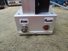
Below: On the side is a power indicator light to verify the little supplimental supply is operating, and the bias adjustment to set the output of the bias regulator circuit for the correct current draw of each complete output section in the amplifier. The adjustment is supplied with a locking nut so the adjustment cannot be accidentally moved once set:
SAM_4206.jpeg

Below: Remembering that this was entirely a junk box project, the box housing the regulator circuits originally housed a transistorized preamp used in a rack that made up a 60's vacuum tube powered Carillon system. The dual heat sink assembly was extracted long ago from a quickly discarded germanium powered receiver, both of whose driver transformers (among other things) had bit the dust. The small AC plug appearing at the end of the cable plugs into the 240's auxillary AC power socket under the repurposed Constant Voltage Output connections socket, and powers the small supplimental supply for the B+ regulator:
SAM_4208.jpeg

Below: Schematic of the two regulators:
MC 240 Regulator.jpg
 
Dave, simple and effective. I like the "adder" transformer. Nice work. The output transformers thank you that they never have to see 460vdc again.

Regarding the 405vdc that was chosen for the regulated B+. I assume that voltage was chosen because the loaded amp connected to 120vac provided exactly that at the output of the choke. In my estimation the voltage could be turned up higher as the 6L6GC's should handle it. I'm not suggesting anyone do this as I would not want to risk an output transformer failure. Of course a different PS would be required. Just thinking out loud here I wonder what the power would be at say 450vdc regulated? A big advantage of the class B operation here is that even at an elevated voltage at idle the bias current would still be very low.

As a side comment, with this regulator I bet you could short out the choke and get an extra 12vdc...
 
I don't have a 240 but I do have a pair of MC30's. Seems like some of the items mentioned in this thread could apply to the 30's. I'll have to read again and more carefully.
 
Rust -- Correct. The 405 volt setting was established because that was the voltage initially produced at the output of the choke when the amplifier was instantly called upon to deliver maximum power output in both channels from a quiescent condition, while operating from a 120 vac line. Under sustained maximum power output conditions, the B+ at that point actually rises to about 410 vdc as the current limiter then continues to heat even more in that scenario, which further reduces its drop. I chose to use the worst case scenario voltage however to maximize the regulator's performance since technically, only 405 vdc is available for an initial transient to draw from.

The regulator could be set for a higher output voltage as the 6L6's routinely see 460 vdc in the stock design without the regulator -- but of course the regulator would ultimately fall out of regulation in that scenario, and the amplifier would produce no greater power output as a result. I left the choke in the circuit to maintain the significant filtering action it provides, and to help absorb the initial power surge at turn on. For the little extra power output that shorting the choke out would provide, I didn't think the advantage outweighed the loss.

55 watts of real world power output from 6L6GCs operating from a B+ source of only 405 volts is already rather remarkable in and of itself, where normally, more like a sustained 475 volts or so would be required in traditional designs. In the Mac design however, the slightly reduced effective reflected plate-to-plate impedance (~3600Ω), the highly efficient output transformers, and the fact that at a full boil the output stage is operating under Class B2 conditions, all combine to make such power output possible.


Nerd -- A significant amount of the information in this thread does in fact apply to the MC 30 -- and really almost more so, since it uses a high drop rectifier tube which only acts to accentuate the high power transient issue even further. At the very least, installing the 1Ω resistor for determining real output stage current draw would allow the output stage to in fact be propery biased, and help to ensure that an unusually low quiescent current draw isn't needlessly piling on to accetuate the high power transient clipping issue even further.

Dave
 
Obviously an extremely different design, but my AB1 6L6 amp with 415v on the plates does right about 23 watts, so a little under half what these do. Just as a point of comparison.
 
Excellent work Dave, you made me realize why I didn’t like any of those McIntosh amps. Might have been the Class B operation as well? I never liked the harmonics in an SET pulling grid current.
I prefer my Fisher SA100 over the MC30 or even the MC40.
My ARC D115 MKII absolutely smokes the 30,40,60,75 MC series and used when I really want to make those Khorns sing.
Have you looked at any improvements the the D115?
 
Maybe thats why I always preferred the sound of 275's over 240's even though both my 240's would put out 55 watts while meeting specs.Mac charts 1.jpgMac charts 1.jpg
 
Thanks for the Mac Clinic graphs Twiiii. The distortion curve at 55 watts is the spitting image of what my own 240 originally produced at those power levels, and now it meets the standard for their SS equipment at 55 watts from 20 Hz to 20 kHz when using the power supply regulator. Mine however did not achieve the level of S/N ratio yours did in both channels until I installed the balanced heater supply modification. It would meet what yours produced in one channel, but not in both until the modification was installed. Based on component serial numbers in my amplifier, my 240 was manufactured about the time yours were being tested at the clinic........

Deaf -- I suspect that you may like a little lower damping factor than the Mac's provide for. The classic Macs all run with a total of about 35 db of NFB (both local and global combined), which produces -- for the vacuum tube realm -- a very high damping factor indeed. Some like that, some don't, although from a strict definition standpoint, an amplifier -- as a device used for driving a loudspeaker -- is technically more accurate in what it does the lower its internal output impedance is. But, that can also make for a rather dry presentation from some speakers........

As for the grid current drawn by the output stage, it is a way, way different animal in the 240 than a triode output stage (PP or SE) draws when grid current commences. The later typically requires a positive grid drive of 20 volts P-P or more with the commensurate grid current that draws when using conventional receiving type power tubes, and much more when using the bigger triode transmitting tubes -- some requiring a small Class A power amplifier to properly drive. In the 240, the pentode operated output tubes are fully saturated when barely driven 4 volts P-P positive, with only a fraction of the grid current drawn that triodes pull. That's why a whimpy little 12AX7 can fully provide all the grid current the 240's output stages need when operated at a full boil.

Pentodes -- when operated as such -- have their faults, and as a result, generally don't make for very good devices to drive a loudspeaker (way too high an output impedance). The Unity Coupled output stage doesn't rectify their faults, but goes a long, long way to cover them up, so that when that expedient is used along with enough reserve power for the needs at hand, they can in fact do their job very well indeed. When pentodes are the chosen power plant, there simply is no other pentode configuration that can produce the power output, efficiency, and low distortion levels that Mac's Unity Coupled output stage can produce.

As stated however, its high performance capability demands equally high performance from the circuit associated with it, or it can suffer when attempting to produce transient power within its steady state power capabilities, but over its rated power capability. Regulating the 240's power supply not only in fact removed that performance limitation, but also for me mentally removed the knowledge of the limitation, so that after all the dust has settled from this project and the bias of anticipation has worn off, I find myself enjoying my 240 more than ever before.

Dave
 
Last edited:
Deaf -- Since you inquired, I also meant to mention that you can read my own ARC D115 adventure here:


A truly wonderful amplifier but a diamond in the rough with dependability issues that Mac ran circles around. I was able to resolve all of those as well so for me it continues to stand as one of ARC's finest efforts.

Dave
 
I love reading all the testing, evaluation, and suggestions for improvement you offer Dave. I need to read thru a few more times for it to stick being a novice with modding. I have a 240 that had an interesting anomaly. When i opened it up to restore it, i found the “unity” circuit un-soldered to the output sockets in one spot. The wire (yellow or white? If memory serves..) was stripped, tinned, then neatly taped to the board behind one of the large film caps!! It sure looked to be intentional. And done by McIntosh.
 
Rude -- If it was a white transformer wire, that is the transformer's NFB winding, so disconnecting it would allow the amplifier to operate, but with the Global NFB circuit disconnected. So configured, the amplifier's input sensitivity would increase by a factor of about X10, and of course distortion and frequency response would all be compromised. But the white leads (one from each transformer) do not connect to the output tube sockets.

If it was yellow leads, these connect to pin 8 of the output tube sockets, and comprise the cathode winding of the Unity Coupled design. If they were simply disconnected in a temporary manner, that might imply one thing -- as in testing the transformers (although these leads do not need to be disconnected to check the status of these transformers) -- but if they were disconnected and neatly tucked away securely, then that implies they were not going to be used. This would be a terrible "modification" to make, and strongly implies whomever made it really doesn't understand how the Unity Coupled output stage operates. I would find it more than extremely hard to assign such a move to the factory.

If such a modification were attempted, it implies that the understanding is that the plate winding acts in the conventional manner as the winding into which all power output is developed, and the cathode winding is just a conventional cathode feedback winding to effect partial cathode coupling ala ARC style. Nothing could be further from the truth. In the Mac transformer, both the plate and cathode windings equally receive the power developed by the tubes, such that if half of this total plate/cathode winding is eliminated, then the resulting load seen by the tubes is 1/4 that when both windings are connected. Operating the tubes into 1/4 of the required reflected impedance (or about 900Ω plate to plate with such a move) would severely overload the tubes, grossly reduce power output, and destroy any pretense of the performance the amplifier once had.

Assuming then that this is nothing more than an ill conceived modification (or unfinished installation of a replacement transformer?), the first order of business with your restoration is to restore or ensure the full execution of the Unity Coupled design!

Dave
 
Are we talking about the output tube socket, or the speaker output socket? Lead unhooked from the speaker output socket would be the NFB lead I'd think.
 
On Mac's vintage stereo amps, the octal output socket is for the 600Ω and 70.7 volt output connections only -- none of the leads there are white or yellow in color, nor are used for NFB. The NFB is taken from its own dedicated winding, while the conventional 4-8-16 Ohm speaker connections only appear at the two black barrier strips, and float relative to ground.

Dave
 
Rude -- If it was a white transformer wire, that is the transformer's NFB winding, so disconnecting it would allow the amplifier to operate, but with the Global NFB circuit disconnected. So configured, the amplifier's input sensitivity would increase by a factor of about X10, and of course distortion and frequency response would all be compromised. But the white leads (one from each transformer) do not connect to the output tube sockets.

If it was yellow leads, these connect to pin 8 of the output tube sockets, and comprise the cathode winding of the Unity Coupled design. If they were simply disconnected in a temporary manner, that might imply one thing -- as in testing the transformers (although these leads do not need to be disconnected to check the status of these transformers) -- but if they were disconnected and neatly tucked away securely, then that implies they were not going to be used. This would be a terrible "modification" to make, and strongly implies whomever made it really doesn't understand how the Unity Coupled output stage operates. I would find it more than extremely hard to assign such a move to the factory.

If such a modification were attempted, it implies that the understanding is that the plate winding acts in the conventional manner as the winding into which all power output is developed, and the cathode winding is just a conventional cathode feedback winding to effect partial cathode coupling ala ARC style. Nothing could be further from the truth. In the Mac transformer, both the plate and cathode windings equally receive the power developed by the tubes, such that if half of this total plate/cathode winding is eliminated, then the resulting load seen by the tubes is 1/4 that when both windings are connected. Operating the tubes into 1/4 of the required reflected impedance (or about 900Ω plate to plate with such a move) would severely overload the tubes, grossly reduce power output, and destroy any pretense of the performance the amplifier once had.

Assuming then that this is nothing more than an ill conceived modification (or unfinished installation of a replacement transformer?), the first order of business with your restoration is to restore or ensure the full execution of the Unity Coupled design!

Dave
It was indeed connected (or supposed to be) to pin 8 of an output tube. And i only realized what was going on after i started removing the original caps. It could not be seen as it was run behind the caps and terminated in tape. So i must assume it was a factory error??… the other output tubes were connected with a similar wire at pin 8. That is how i figured out where it was meant to be soldered in. I did connect it while replacing all capacitors. So strange! I have pics somewhere i will share when i find them
 
Ok i do not want to derail this thread. But here is a pic if my 240 when i was in the process of a recapping/ restoring it. The wire in question is shown in this pic after i removed it from the tape on the board. The amp “appeared” to my eyes to have never been opened previously. And the caps were covering this wire completely. So i do think it was either an error, or intentional at the time of manufacture. But???
 

Attachments

  • IMG_8946.jpeg
    IMG_8946.jpeg
    140.3 KB · Views: 41
Back
Top Bottom
