• The move to the new server is done. There are some software and database maintenance updates in process. This has us passing the hat around to help out. We appreciate any donations. Seriously, even a dollar helps. The payment page may be found here - https://www.audiokarma.org/support.html

THE MC 240: ACHIEVING MAXIMUM PERFORMANCE FROM AN ICONIC DESIGN

Does look rather like it was never connected, doesn't it!

In looking at the pic however, it appears that the Unity Coupled transformer cathode leads are all attached, and that the unattached lead is the lead normally going from the output tube cathode (third tube up from the bottom in this case) that provides the boot strap connection for the driver stage cathode circuit. The other three tubes appear to have their transformer and boot strap connections made at pin 8, but the third tube up only has the transformer connection. What does the other end of that lead connect to? It likely connects to a cap on the component board.

Let us know!

Dave
 
Does look rather like it was never connected, doesn't it!

In looking at the pic however, it appears that the Unity Coupled transformer cathode leads are all attached, and that the unattached lead is the lead normally going from the output tube cathode (third tube up from the bottom in this case) that provides the boot strap connection for the driver stage cathode circuit. The other three tubes appear to have their transformer and boot strap connections made at pin 8, but the third tube up only has the transformer connection. What does the other end of that lead connect to? It likely connects to a cap on the component board.

Let us know!

Dave
Hey Dave. Thanks again for your expertise. I will need to open the amp again to double check the path of the wire in question. But i remember looking at the schematic at the time, than “ohming it out” with my meter, and it went to a junction at a cap (maybe .047 or .47?) similarly to what the three wires did. I did indeed solder it to the octal socket where it should have been. I did not notice any sonic differences after the “correction” if indeed it was not intentionally left flying. I recapped a good friends 240 as a favor and that amp had all the connections at pin 8 intact. As i imagine all 240s should! Lol
 
Yep, then that would definitely be the boot strap connection. At typical power output levels, you wouldn't have noticed any difference at all. But at elevated power output levels (near full power), the side of the push-pull signal that connection represents would have struggled compared to the other side, so performance deterioration would definitely be there, but it likely would have taken test equipment to show the effects of that lead not being connected.

Good luck with your restoration!

Dave
 
I am just not understanding the easiest and safest way to rebias the 240 to set the quiescent current for approx 25ma for each tube without calling in techs.

I know it involves a procedure but am unsure what to do. Not that I don't understand basic mechanics and electronics, but having open 240s and sticking my hands in when running high voltages makes me a bit reticent.
I do love this amp though....just makes me upset that bias can't be set easily for modern tube production standards.

What should I do because I guarantee that only one set here runs in the ballpark of say 28-31ma for each of the four Sylvania tubes when measured with probes.

The JJs I have measure approx 17ma each.

The 6P3S-E measure approx 17ma each but those are different tubes and perhaps regardless of what Michael Samra has recommended to me in the past, I probably won't use them again in this amp. They don't make power. (They can't...don't they put out like 25watts max?)

What should I do? Knowing that we don't live in 1964 anymore and that modern tube production doesn't yield the same electrical results of old bums me out a bit.
 
Last edited:
I am just not understanding the easiest and safest way to rebias the 240 to set the quiescent current for approx 25ma for each tube without calling in techs.

I know it involves a procedure but am unsure what to do. Not that I don't understand basic mechanics and electronics, but having open 240s and sticking my hands in when running high voltages makes me a bit reticent.
I do love this amp though....just makes me upset that bias can't be set easily for modern tube production standards.

What should I do because I guarantee that only one set here runs in the ballpark of say 28-31ma for each of the four Sylvania tubes when measured with probes.

The JJs I have measure approx 17ma each.

The 6P3S-E measure approx 17ma each but those are different tubes and perhaps regardless of what Michael Samra has recommended to me in the past, I probably won't use them again in this amp. They don't make power. (They can't...don't they put out like 25watts max?)

What should I do? Knowing that we don't live in 1964 anymore and that modern tube production doesn't yield the same electrical results of old bums me out a bit.
Your post has a lot to unpack so let's go in your order.
There is no "procedure" to "rebias" the Mc240 unless and when the the bias selenium rectifier has been replaced.
Whatever your prospective output tubes have been measured at or by will not be what they will do in the Mc240.
This link has posts that list what changes are to be made if and when the selenium bias rectifier has been replaced: https://audiokarma.org/forums/index.php?threads/mcintosh-hints-and-kinks.87157/page-2
Making sure that the bias is correct when the bias rectifier has been replaced does involve "sticking" your hand in while the amplifier is energized. IMHO you should seek out a qualified technician to make this change IF it has not already been done. Also, depending on the current condition of the amplifier, a thorough refresh might be in order.
 
Your post has a lot to unpack so let's go in your order.
There is no "procedure" to "rebias" the Mc240 unless and when the the bias selenium rectifier has been replaced.
Whatever your prospective output tubes have been measured at or by will not be what they will do in the Mc240.
This link has posts that list what changes are to be made if and when the selenium bias rectifier has been replaced: https://audiokarma.org/forums/index.php?threads/mcintosh-hints-and-kinks.87157/page-2
Making sure that the bias is correct when the bias rectifier has been replaced does involve "sticking" your hand in while the amplifier is energized. IMHO you should seek out a qualified technician to make this change IF it has not already been done. Also, depending on the current condition of the amplifier, a thorough refresh might be in order.
All that has been done. It has been serviced and has had all parts changed that were recommended to me and sold as a complete kit by Jim McShane. A qualified tech checked the work and this was in 2012.
What I am referring to is Dave's findings using current JJs that idle at less than optimum conditions.
He changed that and that's what I am trying to figure out how to do.
Thanks.
 
Last edited:
All that has been done. It has been serviced and has had all parts changed that were recommended to me and sold as a complete kit by Jim McShane. A qualified tech checked the work and this was in 2012.
What I am referring to is Dave's findings using current JJs that idle at less than optimum conditions.
He changed that and that's what I am trying to figure out how to do.
Thanks.
Everything he did and why is explained in this thread. It is a very technical discussion to be fair, as most of Dave's equipment threads are, and the application of his corrections is best left to those who feel comfortable implementing them.
 
Cherry picking a bit from the thread, this should provide a cliffnotes version of the process, though its not quite a "step by step" guide for implementation.
It was decided that the best way measure output stage quiescent current is to install a 1Ω 1% 0.25 watt resistor in series with each red OPT B+ lead.

there is a pic here where that was done physically

quiescent current was adjusted to 68 mA total per output section by shunting an appropriate resistor across R61

thats how you make the adjustment, I'd probably temporarily clip a 1M or so pot across the resistor, make the adjustment, measure the pot, and install whatever resistor it turned out to be.

this may be spelled out but I didn't find it, so a little further interpretation here. To measure 68mA across a 1 ohm resistor, set your meter to read millivolts, and you're looking for 68 mV. 1mV across 1 ohm is 1mA. Just be aware that this point is somewhere around 450 volts DC to ground.

if all that sounds like voodoo, get someone who is comfortable poking around in tube amps to make the modification and set this for you.
 
Hi Dave,

Thank you for sharing your findings and fixes. I have a question/mod that maybe you can offer some insights based on your experiences with these McIntosh Amps.
Most modern day DACs can put out ~ 5 to 6V differential output from the balanced XLR output. With this amount of output can we eliminate the 1st stage 12ax7 gain stage and mod the 12au7 phase splitter? The DAC will do a better job of putting out a differential output than a 12au7 phase splitter ever will.
And take a differential global feedback into the second stage of the MC240 or MC225 assuming the transformer has a center tap in the independent secondary feedback winding. Will this lower the total distortion of the amplifier altogether?
I happen to see that the newer MC275(from mark V onwards) they cutout the 1st stage and changed the arrangement of the 12au7 tube when using XLR inputs
 
Last edited:
Part of the reason I am asking is because I have a MC225 and also got for a good price an additional set of shorted out MC225 output transformers. I intend to unwind one to figure out the winding arrangement. There’s been conflicting hearsay etc that either the winding is a very simple bifilar or that it is a complicated interleaved design.
 
Last edited:
Also do you have any suggestions of any other types of tubes that could offer lower distortion than the 12au7 12bh7 combination assuming we are free to alter the supply voltages to these stages and change resistor and cap values ie a redesign with better tube types if those exist. And no longer using the 12au7 as a phase splitter and just use XLR inputs. No restrictions to using rare to find tubes at all
 
I don't think you will find a center tap in that secondary feedback winding. At least I didn't on these. FWIW, I did try to clone the MC240 using the Vanderveen Unity Coupled output transformers in a balanced no-phase-splitter arrangement.

I did drop in a Vanderveen Unity Coupled OPT in an unmodified MC30 with good results as documented here elsewhere so the Vanderveen is a good Unity Coupled OPT.

In the case of the Vanderveen's the speaker secondary (there was only one with no taps) had the same turns ratio as the single feedback winding. I used a clone MC275 board with some minor mods and balanced inputs. I had limited success and abandoned the project. Even though the speaker secondary and the feedback winding were the same turns ratio I could not get the symmetric feedback required. Perhaps more work could have resulted in a satisfactory amp. I simply decided to stick with the newer chinese MC275 clone output transformers that have the center tapped feedback secondary's and had good results as documented here elsewhere.

In your case, lacking a dual feedback secondary in the MC240 OPT, start with measuring the feedback turns ratio and see if it matches one of the turns ratios on one of the speaker taps. IMHO messing around with a vintage irreplaceable MC240 output transformer and connecting in this way is inviting disaster if something goes wrong. Better to play around with some clone transformers. I did burn up a Vanderveen during this experiment, lol.

That said, I am a big fan of balanced inputs these days and tube amps with balanced inputs are hard to find. If I were spec-ing an OPT I would opt for dual identical feedback windings either separate or center-tapped. A future project I intend to experiment with McIntosh MA-230 output transformers that have dedicated cathode feedback windings. Rather than connect as cathode feedback I intend to try to use the cathode feedback windings as symmetrical feedback windings to the balanced input stage.
 
I don't think you will find a center tap in that secondary feedback winding. At least I didn't on these. FWIW, I did try to clone the MC240 using the Vanderveen Unity Coupled output transformers in a balanced no-phase-splitter arrangement.

I did drop in a Vanderveen Unity Coupled OPT in an unmodified MC30 with good results as documented here elsewhere so the Vanderveen is a good Unity Coupled OPT.

In the case of the Vanderveen's the speaker secondary (there was only one with no taps) had the same turns ratio as the single feedback winding. I used a clone MC275 board with some minor mods and balanced inputs. I had limited success and abandoned the project. Even though the speaker secondary and the feedback winding were the same turns ratio I could not get the symmetric feedback required. Perhaps more work could have resulted in a satisfactory amp. I simply decided to stick with the newer chinese MC275 clone output transformers that have the center tapped feedback secondary's and had good results as documented here elsewhere.

In your case, lacking a dual feedback secondary in the MC240 OPT, start with measuring the feedback turns ratio and see if it matches one of the turns ratios on one of the speaker taps. IMHO messing around with a vintage irreplaceable MC240 output transformer and connecting in this way is inviting disaster if something goes wrong. Better to play around with some clone transformers. I did burn up a Vanderveen during this experiment, lol.

That said, I am a big fan of balanced inputs these days and tube amps with balanced inputs are hard to find. If I were spec-ing an OPT I would opt for dual identical feedback windings either separate or center-tapped. A future project I intend to experiment with McIntosh MA-230 output transformers that have dedicated cathode feedback windings. Rather than connect as cathode feedback I intend to try to use the cathode feedback windings as symmetrical feedback windings to the balanced input stage.
Hi Rust, good to know someone else contemplated getting rid of the phase splitter function. Also did you see the measurements made on Erin’s corner that the clone MC275(Orsefon) had markedly inferior performance (bandwidth distortion) compared to the MC275mk6. Looks like those China made transformers are neither clones nor an improvement.
 
In my estimation, the simplest solution is to simply purchase either the real MC275 or the clone and plug into the xlr inputs. On the Gordon Gow edition, you can even physically remove the first tube. Can't do that so easy with the later MC275s as that first tube filament is in series with another tube.

Regarding the real McCoy reissue MC75 monoblocks. They're not fully balanced input to output. If you look at the schematic for those they use a different OPT -- one that has a single feedback winding as it uses a phase splitter. If you plug into the xlr inputs the signal is first converted to single ended via...gasp... an op amp!
 
Last edited:
any suggestions of any other types of tubes that could offer lower distortion than the 12au7 12bh7 combination


6CG7 is generally a more linear / lower distortion tube than a 12AU7 with otherwise-similar properties. It does need twice the heater current of a 12AU7 though, so just be aware of that. In a diff pair arrangement I don't know that it will make much difference since there is a decent bit of local feedback in that configuration.
 
6CG7 is generally a more linear / lower distortion tube than a 12AU7 with otherwise-similar properties. It does need twice the heater current of a 12AU7 though, so just be aware of that. In a diff pair arrangement I don't know that it will make much difference since there is a decent bit of local feedback in that configuration.

In my estimation, the simplest solution is to simply purchase either the real MC275 or the clone and plug into the xlr inputs. On the Gordon Gow edition, you can even physically remove the first tube. Can't do that so easy with the later MC275s as that first tube filament is in series with another tube.

Regarding the real McCoy reissue MC75 monoblocks. They're not fully balanced input to output. If you look at the schematic for those they use a different OPT -- one that has a single feedback winding as it uses a phase splitter. If you plug into the xlr inputs the signal is first converted to single ended via...gasp... an op amp!
That’s true if I am going with an MC275. Reason I brought this up is as an experiment to squeeze every last bit of performance from the mc225 and mc240. Especially if I do find out in future after unwinding my shorted set of mc225 transformer that winding arrangement isn’t that complicated. If it is a complicated winding arrangement I’ll give up.
Another thing is I like the MC225 or MC240 better because in the original form it has one stage less than the MC275.
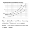
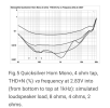
The ultimate aim is not to increase the o/p power of the mc225 or mc240 but to push the absolute distortion from low 10mW to rated power 25/40W down. Aiming to get below 0.1% distortion. And nice flat distortion across freq from say 100hz to 20kHz.
Basically aiming to be as good or better than these measurements for the Quicksilver horn mono amps that has even an o/p impedance of less than 0.2 ohm
1786638362881.png
1786638419571.png
1786638459723.png
And hopefully a distortion profile dominated by 2nd and 3rd order and vanishing or non existence higher order distortion.
 
Last edited:
In my own experience, I’ve found that the ultra low distortion SET with 2 or 3 stages, those that can achieve 0.1 % distortion at the 1mW to 1W, rising gently to ~1% distortion at 10W(clipping at 10% at 20W) and only 2nd, 3rd harmonic present most of the time across frequency band when driving efficient low distortion speakers(90+dB) gave the most life like/magical experience. Most of the time these are also low feedback amps. Only thing I do not like is the type of tubes used and the voltages in these Amps and the amount of heat given off, and the o/p impedance being ~ 1+ ohm creating a low damping issue. The other extreme that achieved the same that I have heard is a circlotron OTL with multiple tubes with some feedback to achieve o/p Z~0.6 ohm….
The drawback with the SET is inability to put out great current drive and woofer control when doing power bass from rock or thundering cannon rumble in the 1812 overture
 
Last edited:
Back
Top Bottom