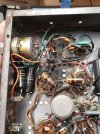
Sound - The two transistors make up the EFB™Grid Bias Regulator, which is a large part of the amplifier's improved performance.
In a pentode tube, the operating point is set as much by the screen grid voltage as it is by the control grid voltage. In typical fixed bias amplifier designs, the screen grid voltage drops fairly significantly at high levels of power output which elevates distortion, and reduces power output. The ideal answer of course is to regulate the screen voltage which certainly helps, but the plate voltage still drops which limits the effectiveness with that type of regulation. Now in the Bogen design, because the plates are powered directly from the high voltage supply, and the screens are powered almost directly from the mid voltage tap of the doubler supply, the relationship between the plate and screen voltage is maintained pretty well as power supply voltages begin to droop. But the control grid voltage remains quite stable as B+ voltage is dropping, which again, upsets the operating point of the output stage, and increases distortion.
EFB solves this problem by causing the grid bias voltage to track in a set relationship to the screen grid voltage, which itself tracks in a set relationship to the plate voltage. With EFB applied then, the main B+ will still droop as power output is increased, but the screen voltage and the control grid voltage will decrease in precisely the same relative amount along with it. The end result is that yes, power output is still lost because of the droop, but because all the elements drop proportionately together, the operating point is maintained in spite of the droop, and distortion drops dramatically. This concept has been proven out in numerous different units, and verified by numerous folks world wide now. The 470K resistor at the base of the inverter transistor connects to the screen grid supply, so that the EFB Control Grid regulator then controls the bias supplied to the output tubes, based on the screen grid voltage applied to the tubes. It's a win-win approach, because compared to traditional high voltage regulators for vacuum tube service, the regulator is quite simple, yet delivers the same amount of distortion reduction that traditional full regulator delivers.
The transistors used are conventional 160 volt PNP silicon devices. The Zener is also a conventional 100 Volt 5 watt device. Mouser part number 863-1N5378BRLG will fill the bill nicely. $0.45 each.
If you have further interest in EFB, you can reference my white paper where I first introduce the concept, which can be found on the web with a Google search for "A New Look at an Old Friend - Tronola".
I hope this helps!
Dave
In a pentode tube, the operating point is set as much by the screen grid voltage as it is by the control grid voltage. In typical fixed bias amplifier designs, the screen grid voltage drops fairly significantly at high levels of power output which elevates distortion, and reduces power output. The ideal answer of course is to regulate the screen voltage which certainly helps, but the plate voltage still drops which limits the effectiveness with that type of regulation. Now in the Bogen design, because the plates are powered directly from the high voltage supply, and the screens are powered almost directly from the mid voltage tap of the doubler supply, the relationship between the plate and screen voltage is maintained pretty well as power supply voltages begin to droop. But the control grid voltage remains quite stable as B+ voltage is dropping, which again, upsets the operating point of the output stage, and increases distortion.
EFB solves this problem by causing the grid bias voltage to track in a set relationship to the screen grid voltage, which itself tracks in a set relationship to the plate voltage. With EFB applied then, the main B+ will still droop as power output is increased, but the screen voltage and the control grid voltage will decrease in precisely the same relative amount along with it. The end result is that yes, power output is still lost because of the droop, but because all the elements drop proportionately together, the operating point is maintained in spite of the droop, and distortion drops dramatically. This concept has been proven out in numerous different units, and verified by numerous folks world wide now. The 470K resistor at the base of the inverter transistor connects to the screen grid supply, so that the EFB Control Grid regulator then controls the bias supplied to the output tubes, based on the screen grid voltage applied to the tubes. It's a win-win approach, because compared to traditional high voltage regulators for vacuum tube service, the regulator is quite simple, yet delivers the same amount of distortion reduction that traditional full regulator delivers.
The transistors used are conventional 160 volt PNP silicon devices. The Zener is also a conventional 100 Volt 5 watt device. Mouser part number 863-1N5378BRLG will fill the bill nicely. $0.45 each.
If you have further interest in EFB, you can reference my white paper where I first introduce the concept, which can be found on the web with a Google search for "A New Look at an Old Friend - Tronola".
I hope this helps!
Dave