

You are using an out of date browser. It may not display this or other websites correctly.
You should upgrade or use an alternative browser.
You should upgrade or use an alternative browser.
The Mighty Bogen MO-200A
- Thread starter dcgillespie
- Start date

Plim2 -- In the MO-200A, the quiescent plate voltage is very typically about 765 vdc, falling to still well over 700 vdc at a full tilt. Now, it is typically possible to operate power tubes at well over their rated plate voltage -- under quiescent conditions! But remember that under maximum dynamic conditions, the peak plate voltage will be nearly double the quiescent voltage, which makes things start to get interesting real quick.
Back in the day, the biggest element contributing to the metal 6L6 maximum plate voltage rating was the material used to manufacture the base of the tube (it was still a factor (but less so) by the end of the tube era). Most tubes simply could not reliably handle over about 400 volts, and not have flash-over under high level dynamic conditions. More specifically, at the time it was not the internal tube structure that was the biggest factor in determining the maximum plate voltage rating for a tube. As a perfect example of this, consider the metal 6L6 and the 807 tube -- both manufactured during the same time period, with both using absolutely identical internal element structures. The difference? The metal 6L6 brings its plate connection out to pin 3 on the base with a 360 volt maximum rating, while the 807 brings its plate connection out to a plate cap on the top of the tube, for a whopping 750 volt maximum rating. This way, the base of the 807 sees no more than 300 vdc (the screen grid's max rating for the tube), which is only slightly greater than the screen grid rating for the metal 6L6 tube -- again, because the wider spacing of the 807s base pins would allow for a higher rating -- while the high plate voltage is removed from the base connections. Even modern 6L6GC or 7581 tubes would be quite challenged in the MO-200A when asked to produce maximum possible power. Under typical garden party use conditions however, they would likely be just fine.
Sound -- nothing replaces the absolute capability of a distortion test-set, but the next best thing would be to use Gadget's approach -- except that I would hang the scope probes on the plates of the output tubes. This will then let the AC adjustment take into account their individual characteristics as well. That then will just leave the OPT -- which will normally be pretty well matched on each side of the push-pull signal, but I've seen plenty of times when it is off by a percent or two as well.
Dave
Back in the day, the biggest element contributing to the metal 6L6 maximum plate voltage rating was the material used to manufacture the base of the tube (it was still a factor (but less so) by the end of the tube era). Most tubes simply could not reliably handle over about 400 volts, and not have flash-over under high level dynamic conditions. More specifically, at the time it was not the internal tube structure that was the biggest factor in determining the maximum plate voltage rating for a tube. As a perfect example of this, consider the metal 6L6 and the 807 tube -- both manufactured during the same time period, with both using absolutely identical internal element structures. The difference? The metal 6L6 brings its plate connection out to pin 3 on the base with a 360 volt maximum rating, while the 807 brings its plate connection out to a plate cap on the top of the tube, for a whopping 750 volt maximum rating. This way, the base of the 807 sees no more than 300 vdc (the screen grid's max rating for the tube), which is only slightly greater than the screen grid rating for the metal 6L6 tube -- again, because the wider spacing of the 807s base pins would allow for a higher rating -- while the high plate voltage is removed from the base connections. Even modern 6L6GC or 7581 tubes would be quite challenged in the MO-200A when asked to produce maximum possible power. Under typical garden party use conditions however, they would likely be just fine.
Sound -- nothing replaces the absolute capability of a distortion test-set, but the next best thing would be to use Gadget's approach -- except that I would hang the scope probes on the plates of the output tubes. This will then let the AC adjustment take into account their individual characteristics as well. That then will just leave the OPT -- which will normally be pretty well matched on each side of the push-pull signal, but I've seen plenty of times when it is off by a percent or two as well.
Dave
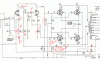
So I was thinking, the testing the original amp was overloading the input so I research a little and this is what I put down..I noticed the plate on the 12ax7 section was really low somewhere around 60..isn't that kinda low?
Attachments

Stumbled upon this amazing thread, had missed it first time around.
Learned so much, but was saddened to see two distinguished members are no longer with us. I already knew it, but it still stings to see it there in black/white.
Also, never knew Tinkerbelle powerlifted. That's awesome.
Such a neat thread, wish I was tech-gifted, but that's just not the case.
Learned so much, but was saddened to see two distinguished members are no longer with us. I already knew it, but it still stings to see it there in black/white.
Also, never knew Tinkerbelle powerlifted. That's awesome.
Such a neat thread, wish I was tech-gifted, but that's just not the case.
Dave you bring up a great point, I have seen output transformers with mismatched resistance from center tap to the outer windings. That would be a in balance that would throw you off chasing...I have seen transformer specs written with the resistances almost 10-20 ohms off...but that was a time when you can drink and drive too! 
Sound -- The numbers you are referring to is the DC resistance for each side of the primary winding -- which is not what I'm referring to. Invariably, because of the geometry of the winding, one side of the primary winding will always show a greater DC resistance. But what I'm referring to is slightly unequal impedance (likely turns ratio) on each side of the winding -- where in if you applied an AC voltage to one side of the primary and measured the output on the secondary, and then applied the exact same AC voltage to the other side of the primary, the output voltage on the secondary would be slightly different. That's the difference I'm talking about. Technically, a difference in DC resistance will cause one tube to develop slightly (but imperceptibly) less power output, but a difference in impedance will necessitate a slightly unequal drive signal be applied to the transformer -- at any power level -- for optimum cancellation to occur.
For any direct coupled Concertina phase inverter, the ideal previous stage voltage is 25% of the B+ supply powering the phase inverter stage.
Dave
For any direct coupled Concertina phase inverter, the ideal previous stage voltage is 25% of the B+ supply powering the phase inverter stage.
Dave

Great amps I had a pair of these once I traded away for other gear.Just as I get everything cleaned up from my Fisher X-1000 project (and related projects), this sucker showed up on my doorstep yesterday. The mailman was none to happy to put it there, but exceedingly happy once he had. I had similar feelings getting it downstairs to the lab. This is one heavy sucker!
I've never seen or heard one of these amps in person, but have read all manner of glowing sonic and theoretical evaluations, have seen a thread with a rebuild or two, and have even seen a number of threads where work was at least started on one -- or on it's smaller MO-100A brother. But still, while the specs certainly imply there should be good performance, and the sheer mass of the transformers scream that this thing should absolutely get'er done (a little southern speak there for ya), no one that I am aware of has ever taken a stock unit, put it through its paces to document the base performance of the unit, and then developed a plan accordingly to make the best of what it is as separated channels for stereo operation. This thread should go a long way to address this effort, as that is exactly what was requested of this unit.
The initial plan then will be:
1. Thoroughly evaluate the tubes provided, and (hopefully) produce two matched quads of good tubes -- from the batch of 16 that were sent. If we can't get past this step, then the whole scope of the work immediately changes.
2. Evaluate the unit itself, and address any needs to produce proper operation of the stock design.
3. Develop a base line of information regarding power bandwidth, distortion, and frequency response, as well as other lesser informative pieces of information.
When this work is finished, then a workable plan can be developed to maximize the unit for what it is, based on the known performance of the stock unit. Until that is known, any effort of improvement is just shooting in the wind.
For those interested, some basic information might be of value at this point. This unit was designed with two principle objectives in mind:
1. To work as a 200 watt sound distribution amplifier, with the necessary 25 volt and 70 volt connections provided for the constant voltage speaker systems, or
2. To provide a 200 watt 115 vac source of power to operate variable frequency devices such as shaker tables and the like.
Also, a conventional 8 ohm output tap is provided as well. However, one of the greatest features of this amplifier is the duty cycle it was designed to operate under: It was designed to produce full power output on a continuous basis.
When you consider the tubes used, it only takes a pair to produce 100 watts of power output (of plate power anyway). Therefore, to produce (essentially) 200 watts, only 4 tubes are really required. In fact, in the production amp world, there are plenty of 200 watt amps using just 4 6550s, 4 KT88s, and so on to produce that power level.
By using 8 similar type tubes in this amp then to produce the same power level, the necessary current draw through each tube is halved, lowering dissipation levels in each tube under full power conditions, and extending tube life.
I don't want to get ahead of myself, but considering the revised operating environment and cost of these tubes, one possibility is to simply remove a pair out output tubes in each "channel". Each channel would still produce nearly the same amount of power output, because the OPT primary impedance is based on a single pair of tubes producing 100 watts. That's why a quad of tubes in each channel produces no more power than a pair does, but simply halves the current through each tube to produce that power level.
In a different thread, I also mentioned an alternate output connection possibility for a much better 8 ohm match configuration than the 6.25 ohm connection does that is commonly mentioned -- the same alternate connection that Tom Bavis also mentioned from his testing on one of the OPTs used in these units.
Tube testing is underway now, with initial results in the next post. For now, pics include:
1. Get a jack or reinforced table to work on this one. It gives you a workout just moving it around on the bench!
2. This one is in pretty nice physical shape. Plenty of cooling holes provided to allow it to do its intended job on a continuous basis.
3. Not too bad. But somebody has been here before me.
4. The power supply has had the can caps replaced recently, and has been rebuilt in general. But the work is of very questionable quality: For an amplifier of this size and power level, this work is inviting all manner of big and potentially expensive problems.
5. Clearly, something blew up at some point.......
So, my work is cut out just to develop a base line -- but it should be interesting. More soon!
Dave
Regards Snow

rpampt
Analogeous Vinylitis
Don't frequent AK as often these days, but the Red Hot Rod still continues to perform flawlessly and politely. It's only doing tweeter duty in a tri amp system, but with some plans to throw it back into full range duty with some type of horn setup. Nice to see the Bogans are still getting some love. It's entertaining reading the brilliance of Dave G, gadget and others. Keep it up!!!
Dave question and opinion, do you think a output transformer transplant be a better option to the original output with your upgrade 6550's?
What's you opinion on Hammond outputs?
Which would be a better primary impedance for your upgrade, hammond offers 2, 5k@100w or 4.3k@60w?
Thanks John
What's you opinion on Hammond outputs?
Which would be a better primary impedance for your upgrade, hammond offers 2, 5k@100w or 4.3k@60w?
Thanks John
Attachments

The stock circuit with stock iron doesn't perform too well, but modified its quite good.
The Mighty Bogen MO-200A
Not honestly sure if the Hammond transformers would give you any advantage.
It will produce 100 watts RMS from 26 Hz to 20 kHz into 8 ohms, with both channels driven. Mid-band distortion is typically about .35% at 100 watts, while at the frequency extremes, it rises to about 2.5% at this power level. Frequency response is -1 db @ 50 kHz, and -.2 db at 20 kHz.
The Mighty Bogen MO-200A
Not honestly sure if the Hammond transformers would give you any advantage.
Not to disparage Hammond, but their specifications are deceiving. There is a Grand Canyon of difference between performance stated as "Frequency Response 30 Hz to 30 kHz at Full Rated Power", and the specifications of high quality vintage power amplifiers. The problem is, Hammond's specification gives no reference to distortion. I'm not talking about the distortion produced by the amplifier circuit, but by the transformer. More specifically, Hammond transformers generally perform well at low frequencies, and Hammond plays on that fact in their marketing. But notice that other than the specification above, there is zero information about their HF performance -- which in my experience is poor, and particularly so in their larger transformers, where the geometry of such transformers stacks the deck against good HF performance.
A specification that is brutally honest would be one such as: Undistorted Power Bandwidth (or simply Power Output): XX Watts RMS from 20 Hz to 20 kHz, with no more than X% THD. This specification gives you the full expectation that the amplifier -- and by extension the transformer -- will deliver fully as much power output at 20 kHz as it will at 20 Hz, and do so with a stated level of distortion. With the Hammond transformer, there's a lot of implied performance, but in my experience, Hammond transformers have trouble handling more than 10 db of NFB, and a full power 20 kHz sine wave has little resemblance of such -- at least in transformers the size to the Bogen units. The internal winding capacitance at high frequencies is so great as to serious reduce power output at 20 kHz.
Side Bar: As output transformers become physically bigger and bigger, the winding capacitance grows larger and larger, presenting more and more of an additional load on the tubes. Special winding techniques developed by such early transformer pioneers like Hafler, Keroes, McIntosh, and the Peerless group enabled the development of transformers that could reliably deliver full undistorted power output across the entire audio bandwidth (20 Hz to 20 kHz), but transformers of about 100 watts input rating typically represent the practical limit to which such performance can be reached. Above that power level, transformers are usually designed to favor a portion of the bandwidth to maximize their performance within the bandwidth they serve.
Against this, the Bogen transformers are superb units, with the 6550 version of the modified amplifier delivering a full 100 watts RMS at 20 kHz, with only 3.8% THD, while also delivering 100 watts RMS at 30 Hz with only 2.7% THD. This is remarkable performance for an industrial amplifier and for the Bogen transformers -- which also allow for Absolute Stability into any load while operating within a 17 db NFB loop. I serious doubt that the Hammond offerings would even know where to begin to produce this performance level. But note too that the Bogen transformers begin to have significant winding capacitance, and reach the end of their LF inductance limits as well, as converting back to 8417 tubes with all else equal in the modified version for those tubes, has distortion at 30 Hz rise to 5.2% at 100 watts, while maximum power output at 20 kHz has now fallen to 78 watts RMS, with distortion elevated to 8.7% at that frequency and power level. The sole reason for this is because the 8417 runs out of current handling steam, while the 6550 can handle notably more, allowing it to develop more power at lower distortion with a given transformer when the effects of limited inductance and winding capacitance are reached.
Again, I do not mean to disparage the Hammond product, as I'm sure they fill the need in some applications quite well. But when it comes to truly high fidelity performance -- as defined by those who developed and defined the term -- that is simply not a sand box they play in. That the Bogen transformer performs as well as it does, particularly considering the application it was designed for, is a testament to Bogen's commitment to high quality -- their driver circuit notwithstanding!
Dave
A specification that is brutally honest would be one such as: Undistorted Power Bandwidth (or simply Power Output): XX Watts RMS from 20 Hz to 20 kHz, with no more than X% THD. This specification gives you the full expectation that the amplifier -- and by extension the transformer -- will deliver fully as much power output at 20 kHz as it will at 20 Hz, and do so with a stated level of distortion. With the Hammond transformer, there's a lot of implied performance, but in my experience, Hammond transformers have trouble handling more than 10 db of NFB, and a full power 20 kHz sine wave has little resemblance of such -- at least in transformers the size to the Bogen units. The internal winding capacitance at high frequencies is so great as to serious reduce power output at 20 kHz.
Side Bar: As output transformers become physically bigger and bigger, the winding capacitance grows larger and larger, presenting more and more of an additional load on the tubes. Special winding techniques developed by such early transformer pioneers like Hafler, Keroes, McIntosh, and the Peerless group enabled the development of transformers that could reliably deliver full undistorted power output across the entire audio bandwidth (20 Hz to 20 kHz), but transformers of about 100 watts input rating typically represent the practical limit to which such performance can be reached. Above that power level, transformers are usually designed to favor a portion of the bandwidth to maximize their performance within the bandwidth they serve.
Against this, the Bogen transformers are superb units, with the 6550 version of the modified amplifier delivering a full 100 watts RMS at 20 kHz, with only 3.8% THD, while also delivering 100 watts RMS at 30 Hz with only 2.7% THD. This is remarkable performance for an industrial amplifier and for the Bogen transformers -- which also allow for Absolute Stability into any load while operating within a 17 db NFB loop. I serious doubt that the Hammond offerings would even know where to begin to produce this performance level. But note too that the Bogen transformers begin to have significant winding capacitance, and reach the end of their LF inductance limits as well, as converting back to 8417 tubes with all else equal in the modified version for those tubes, has distortion at 30 Hz rise to 5.2% at 100 watts, while maximum power output at 20 kHz has now fallen to 78 watts RMS, with distortion elevated to 8.7% at that frequency and power level. The sole reason for this is because the 8417 runs out of current handling steam, while the 6550 can handle notably more, allowing it to develop more power at lower distortion with a given transformer when the effects of limited inductance and winding capacitance are reached.
Again, I do not mean to disparage the Hammond product, as I'm sure they fill the need in some applications quite well. But when it comes to truly high fidelity performance -- as defined by those who developed and defined the term -- that is simply not a sand box they play in. That the Bogen transformer performs as well as it does, particularly considering the application it was designed for, is a testament to Bogen's commitment to high quality -- their driver circuit notwithstanding!
Dave
Great explanation love it..so with that I have a couple altec chassis I like to use with your 6550 version in my sound room, but there are no trannies on it...in your opinion what transformers would be the best to incorporate in the chassis that are great performers, edcor? With you expertise what would you use?
Agreed. The typical offerings I've seen from the usual go-to transformer manufacturers today are not much more than dressed up guitar amp transformers. The Dynaco clone transformers however, are the real deal.
Dave
Dave
Dave I read the tread again, what a wonderful tread...I consolidated all your work on this project to a word doc. to make easier to read and comprehend...unfortunately I cant post since it is 17 meg file and 122 pages of excellent reading. if you like I can forward to you but will have to do email it to you or anyone else..I was able to upload to my soundude@gmail.com so I can just insert your email...
But I do have questions since I read it again...
I'm confused at the connection "C"...why does the bias, regulator base return back to the screen supply? I probably read it in the tread but didn't absorb...
Also the 2SA1013 is this a regulator, stacked by another coming from the screen supply? to help regulate the bias in case of voltage dip?
One more thing the Zener in the 430v supply for the af and phase splitter stage would you have a part number for it?
Thanks John
But I do have questions since I read it again...
I'm confused at the connection "C"...why does the bias, regulator base return back to the screen supply? I probably read it in the tread but didn't absorb...
Also the 2SA1013 is this a regulator, stacked by another coming from the screen supply? to help regulate the bias in case of voltage dip?
One more thing the Zener in the 430v supply for the af and phase splitter stage would you have a part number for it?
Thanks John