• The move to the new server is done. There are some software and database maintenance updates in process. This has us passing the hat around to help out. We appreciate any donations. Seriously, even a dollar helps. The payment page may be found here - https://www.audiokarma.org/support.html

The Mighty Bogen MO-200A

I happened to be in the shop and saw the post. It was easy enough to just pop the bottom off and look since they were sitting nearby.
 
I would be curious, if with with the proper feedback,if the amps could be made into a slightly lower power Hi Fi amp.
Responding before reading the whole thread, but Dave G mentioned reducing drive impedance( and its not being possible with PPP output stage ).

I must disagree; plate to grid FB across the output tubes and their driver will do that. So, I propose a pentode LTP, and the use of the CT 70V winding for cathode FB. Add to this doubling the idle current to bring up the plate dissipation to 20W/tube...and hopefully doing it on an individual basis so exact matches are not needed.
cheers,
Douglas
 
My output transformers in my MO100A have different color code. Anyone have any tips?

what colors do you have? Mine matched Dave's schematic, but some of the colors were kind of faded and took a little interpretetion. Basically everything was some shade of brown. It was not that difficult to ohm check what wires were on a common coil and figure out what was what.


since I'm currently running mine in my main rig and have been for the last month or so, I can tell you they do not suck. The bottom end on these things is just impressive, and they don't lack for top end either.
 
Guys thank you for the fast reply.
I am back at work this morning and I will get back to you when I get home.
I really thought this thread was dead.
I really can not believe I got a reply on Christmas.
You guys on this thread are truly a helpful group.
Johnny
 
quiet day at home. Don't have kids and the more extended family was off elsewhere. You caught me sometime between TV shows.
 
Plenty of kids and grand kids -- but they were all over here on Christmas Eve so they could be at home on Christmas Day with the little ones.
 
there is actually a complete MO-200a with a full set of 8417's listed for sale in BT currently at a reasonable price. I don't need another project but I will admit there is some temptation. If not for the fact I have a pair of rebuilt running MO-100a's, I would probably be a lot more interested. Not mine, and no affil, just a casual mention in hopes that someone will buy it so I don't have to add yet another thing to my project queue.
 
I looked at my opt’s and I do in fact have the correct color wires I was unable to see them buried in the corner under the power wires.
I now have 3 mo100a’s to play with though 2 have had a melt down at some point.
Question, can I use a small 120/120v isolation transformer instead of the 120/6v transformer turned backwards? It seems to accomplish the same thing.
Thank you,
Johnny
 
don't see why not. As long as you end up with a bias supply voltage in the right general range it should be OK. Might need to tweak a resistor value since the AC output voltage will probably be higher on an iso trans than the reversed 6v transformer. That circuit uses very little current so it doesn't need to be much of a transformer. Space is a bit of a premium inside of these so just watch its not physically too big. I had to downsize the choke for my 100A's to fit them inside.
 
Thanks gadget73.
The reason I ask is because I have a bunch of torrid antenna Baluns that I have use for mA iso transformers in the past. They are pretty heavy duty for what they are. Will test before I implement because I am not as savvy as the designers here.
 
Thanks gadget73.
The reason I ask is because I have a bunch of torrid antenna Baluns that I have use for mA iso transformers in the past. They are pretty heavy duty for what they are. Will test before I implement because I am not as savvy as the designers here.
Ferrite blends are formulated for bandpass frequency ranges and purpose.
 
true, and the core might be lossy when used at 60hz but for the couple of ma it needs to supply that may not really matter.
 
Hello Everyone, I am not a newbie but haven't posted anything since I joined long time ago. Just good reading..I was searching around because I pulled my bogens out of the darkness since I moved to my new house..Since I was a boy I worked with my dad, he worked for a tent chair company..well he also did sound reinforcement for graduations at colleges in north jersey. We set up football fields with huge circus tents and put speakers on every other pole under the tent. Anyway we used these bogen mo200a's..they had ALOT of these amps and the tubes for them and I was the guy that had to hook them up...I was a audiophile in the making and self taught audio from the age of 8...all that was around mostly tubes and they fascinated me. Long story short, when transistors came about they started buying bogen SS booster amps. so in all the years working there I took the broken mo's home to repair...at least 6 wound up in my closet and of course becoming a working man forgot about them till I met my significant other and moved out. 35 years later I still kept toting them around, repaired and used for about 30 something years I still have them and use them on my infinity"s RS4.5 speakers they eat up amps but not the bogens so they are always around, till I got a crown PSA2 amp to power them. now they are boxed up in the basement and I remember reading about stabilizing the amp over 20 years ago. I remember the bias would fail and would heat the screens till they broke and blew the plate resistors and the power supply caps would leak and short.

So I was searching the stabilizing article I seen many years ago and stumbled onto this tread.
I want to applaud Dave for the wonderful work he has done in altering this amp. Great job and wonderful read...Its great to see that there are still experienced troubleshooters out there.
I have 5 of these units and i converted one over 20 years ago to stereo amp just buy separating the cathode resistor, (MO100 Schematic), and separating the outputs like you did and they served me for many years that way...2 - mo200's on the bottom end and the stereo conversion on the upper levels they served me well for alot of years...Foot toaster during winter..and 2 on the shelve for all those 20 years waiting to be converted to 6550's using the stromberg carson amp APH-1200 schematic...where does the time go! Anyway I'm rounding up my amps to put back on my infinities and I like to keep all the tubes in place. I dont have all the fancy equiptment left but a signal generator tube based, a tektronics scope and a trans-conductance hickok tester...

So Dave my question for you would applying some of you work to the full amp stabilize it with all the 8417 tubes?
should I use your loaded NFB scheme?
also I couldn't grasp what you did to balance out the phase inverter to rid the distortion from being applied to the outputs i know you said they were shifting positive. Printed the whole tread to reread!
I was thinking of your bias trim circuit but that be alot of work for each pair of tubes so would building a stable adjustable bias circuit with a separate supply like you did and use 4 trim-pots on the cathodes of each pair to balance cathode currents be good?
I would like to get the distortion lower and better bottom end while bringing the HF power bandwidth back with minimal invasiveness of redesigning the entire amp like you did.

Thanks for all you hard work and efforts, sure everyone in this tread is applying your accomplishments to their amps as well...
 
Thanks for the kind words! It sounds like you've done your share of time with these Bogen sound support amps. I'm curious as to the article you had seen on "stabilizing" these Bogen amps -- primarily curious as to what you mean by term "stabilizing". Was this an article per chance on how to prevent the amplifiers from blowing out their plate stopper resistors -- or something else? As to your questions and comments, I'll taken them in no particular order:

1. The problem with the original design is that the AF Amplifier section of the driver tube would run out of bias before it generated enough drive voltage (~ 40 volts P-P min) to develop full power output in the output stage. When that happened, it would cause a very hard and pronounced clip at the output of the AF stage, as it is magnified by the loss of any additional NFB beyond that point to help correct the event. That is, up to the point of input overload, the only reason that the input signal hasn't already overloaded the input stage (i.e. the input signal already being much greater in amplitude than the static bias voltage for the stage) is because of the the presence of NFB being inserted into the stage. When the overload point is finally reached (peak value of input signal exceeds the combined value of static bias and peak NFB signal), no further NFB is produced because by definition, the stage can produce no further increase in output amplitude to ultimately produce it. This means that any further increase in input signal at that point then immediately starts to over-drive the AF stage -- which then causes its average plate voltage to drop due to the asymmetrical way in which the stage overloads. This event, in conjunction with the very large R/C factor coupling the AF Amplifier and Inverter sections, then causes the Inverter section to be temporarily way over-biased, ultimately causing the sound to fade in and out during the overload period, as the overload itself and R/C factor interact to upset the normal operation of the inverter stage. By increasing the amount of static bias for the AF Amplifier stage, its overload threshold is increased beyond the overload point of the output stage (i.e., the output stage overloads first), which then eliminates the problem altogether: The AF Amplifier stage maintains linear operation throughout the entire power output capability of the amplifier, which keeps its average plate voltage constant, when then keeps the phase inverter stage from otherwise moving in and out of linear operation.

2. I am really quite certain, that -- as opposed to bias supply failure (which I have seen little of) -- the real reason that the 39Ω output tube plate stopper resistors were blown out with such frequent regularity in these amplifiers is because of the very asymmetrical way in which the amplifier overloads when overload is reach as explained above. This causes huge and very abnormal transient currents to occur in the output transformer, which then back feeds into the plates of the output tubes, with the poor resistor in between these two opposing forces of energy. A bias supply failure would certainly take out the output tubes -- but would only (at best) overheat the plate stopper resistors for a short period. Against this, virtually all of the stopper resistor failures I've seen don't involve overheated resistors, but physically damaged ones (i.e., cracked) -- the type of damage that only wildly excessive energy causes.

3. Adding resistance to the cathode circuit of a Class AB amplifier design is never a good idea. The resistance is directly in series with the current path flowing through the OPT primary winding, which reduces power output. Resistance here should therefore be kept as small as possible, acting only as a fusing element and for the purpose of measuring current flow, with quiescent current being adjusted by way of the negative voltage applied to the control grid.

4. Remember that these amplifiers were designed for a specific purpose, with original design decisions then based on that purpose. In re-purposing these amplifiers for an alternate use, many of those decisions then must be examined as they relate to the new intended purpose. New design decisions needed to be made so that just as the original design was an engineering exercise to achieve its intended goal, so was the effort to achieve the re-purposed goal presented here. How much of the change you make in going from one design exercise to the other will determine your success in the final outcome.

I hope this helps!

Dave
 
Thank you Dave
Yes I have had many years with these amp and as I have used them for years without any issues, I used a few of the vent holes to mount cathode test points to test balance before operation.
The article I was looking for had to do with grid stop resistors and parasitic oscillations, if I recall it was the control grid that would start to overload when the amp was driven over the point of bias voltage sending them positive and draw current till they disintegrated and shorted..
I know the bias is low on these tubes due to the high trans-conductance and the better choice would be something with a lower trans-conductance to handle the drive voltages without going positive then into overload.

I was always one to use a loaded tap for the feedback to keep the linearity in the af stage but I dont understand the separate winding for the FB...larger r/c to keep the 17db...
I was thinking that the fb loop was always a issue driving the amp into overload off the 70v tap as opposed to the 25v tap with the inductive load to tame the transients to the af stage.

How was the amps distortion if the fb was open, is there possibility of it being unstable?
Any other issues that may be encountered is the instability at the low frequencies, possible motor-boating and oscillations with the fb removed?

Another thing I took advantage of in the amp is the screen switching to put the amp in standby so there was no load on the tubes during intermissions.

I really haven't seen many engineers use this tube in designs probably due to its late entry when transistors were introduced...less than a handful. i'm sure if it had a history like the EL34 or the 6L6 there would of been better designs..

I noticed the the af section doesnt have a cathode capacitor probably to much gain, but it would possibly enhance frequency in the lower regions, most likely have to reduce the fb to reduce the gain..

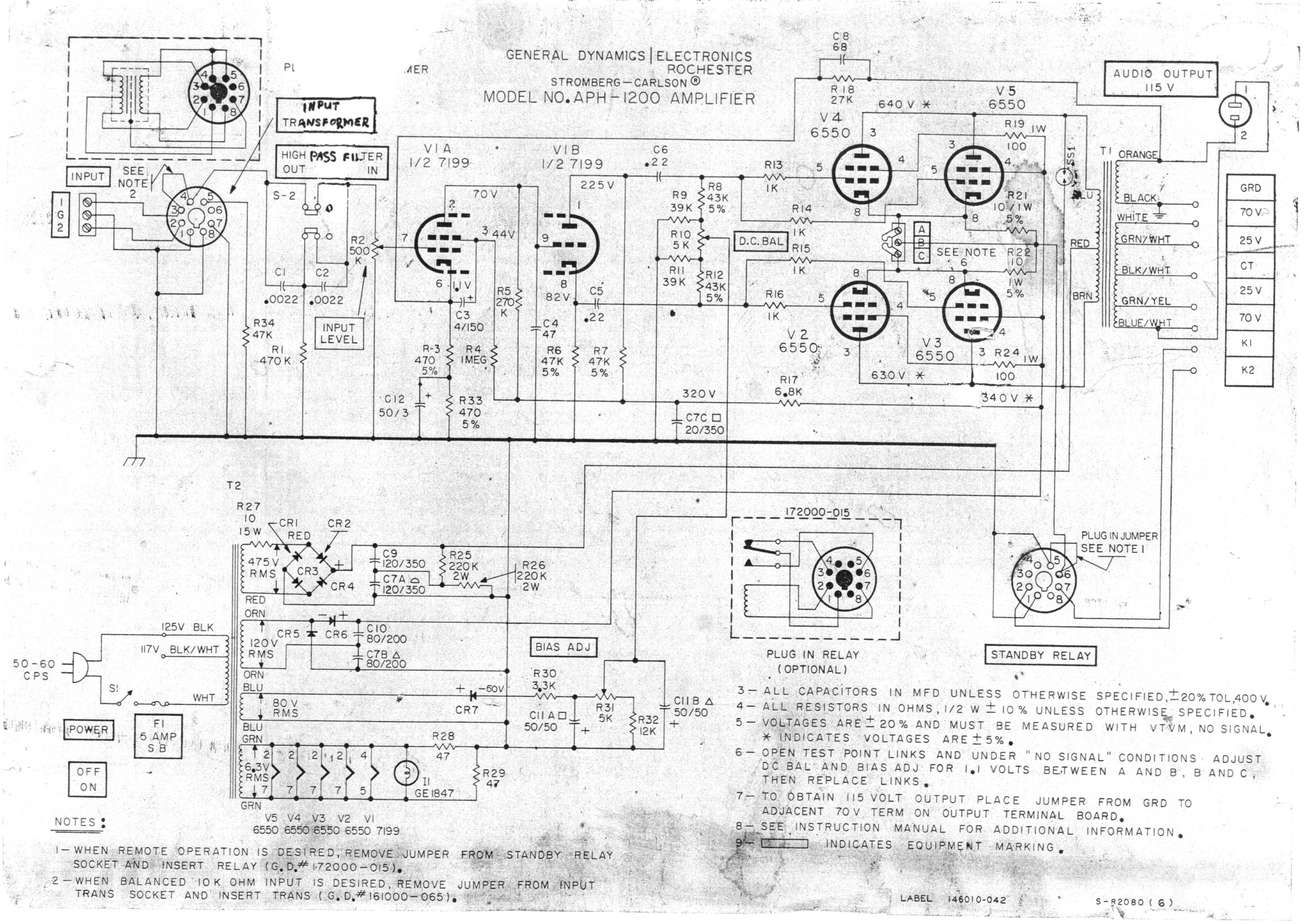
Another thing I been studying the Stromberg APH 1200 schematic and seen they applied separate plate and screen supplies, screen supply is doubler design that also feeds the front end, what do think about this, besides the noisy 7199?
What do you think to incorporate on the chassis?


aph1200.jpg
 
Back
Top Bottom