Hi Paul -- Anytime you parallel circuits, unequal sharing and resulting oscillations are always a possibility. This is the reason (for example) that push-pull parallel output stages typically use resistors to connect the various elements of the output tubes into the circuit to help balance out the currents between the two tubes on each side of the push-pull signal. This helps to prevent the two tubes from fighting each other, and prevents potential oscillation in the process.
As for the instability noted, there is a good possibility that the transformers played in to the instability produced. But it may not be from the paralleled output connection. When typical output transformers are driven beyond their basic ability, coupling starts to suffer, and oscillations can always form as a result. It may also be that output wiring (although in stock condition), and or the measures taken to prevent general parasitic oscillations need to be increased to tamp it down. The only way to know for sure if the paralleled amplifier connection is a factor is to decouple the two amplifiers and recheck each one individually under the same equivalent power/load condition.
I suppose there is a practical limit to stacking units -- if only that the output impedance falls too low below the load impedance presented to the stacked array, which would not be good. More testing would be needed to know if stacking actually causes the oscillations to occur that were presented. I am inclined to think that the oscillations observed were a product of the individual amplifiers rather than their paralleled connection. They were only present at frequency extremes were the unit became transformer challenged.
Preventing such oscillations, and maintaining the full power and low distortion characteristics of mid band performance is primarily about the build of the OPT. Everybody had their own unique approach, but maximizing coupling, and minimizing capacitive loading is the name of the game. Core design, winding pattern, amount of interleaving, and materials used all play into it. That is why quality output transformers -- and particularly high quality high power output transformers -- can get real expensive, real quick.
Remember that frequency response is one thing, as it is measured at a low (1 watt) power level. An extended frequency response ultimately allows for stable negative feedback to be put in place, without the measures to stabilize it causing concerns down in the audio spectrum.
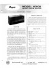
What we have been primarily discussing is power bandwidth -- the bandwidth within which the amplifier can produce full power output. For the Bogen MO-200A, this was basically 30 Hz to 10 kHz. I am not familiar with the VAC 450 to know of its power bandwidth performance. However, the more lower impedance output tubes you can use, the lower the primary impedance of the output transformer becomes, and the greater the high frequency response can be for a given transformer size. It might very well be that this is the approach used by VAC.
Anytime you can lower drive impedance, the LF frequency performance of the output transformer improves. Since this amplifier is already a PPP unit, that option is out. However, PPP triodes in class A2 would lower the drive impedance notably, and the A2 mode of operation would preserve a good deal of the power output. Such a design however would likely not fit in the 200's chassis.
I hope this helps!
Dave
As for the instability noted, there is a good possibility that the transformers played in to the instability produced. But it may not be from the paralleled output connection. When typical output transformers are driven beyond their basic ability, coupling starts to suffer, and oscillations can always form as a result. It may also be that output wiring (although in stock condition), and or the measures taken to prevent general parasitic oscillations need to be increased to tamp it down. The only way to know for sure if the paralleled amplifier connection is a factor is to decouple the two amplifiers and recheck each one individually under the same equivalent power/load condition.
I suppose there is a practical limit to stacking units -- if only that the output impedance falls too low below the load impedance presented to the stacked array, which would not be good. More testing would be needed to know if stacking actually causes the oscillations to occur that were presented. I am inclined to think that the oscillations observed were a product of the individual amplifiers rather than their paralleled connection. They were only present at frequency extremes were the unit became transformer challenged.
Preventing such oscillations, and maintaining the full power and low distortion characteristics of mid band performance is primarily about the build of the OPT. Everybody had their own unique approach, but maximizing coupling, and minimizing capacitive loading is the name of the game. Core design, winding pattern, amount of interleaving, and materials used all play into it. That is why quality output transformers -- and particularly high quality high power output transformers -- can get real expensive, real quick.
Remember that frequency response is one thing, as it is measured at a low (1 watt) power level. An extended frequency response ultimately allows for stable negative feedback to be put in place, without the measures to stabilize it causing concerns down in the audio spectrum.
What we have been primarily discussing is power bandwidth -- the bandwidth within which the amplifier can produce full power output. For the Bogen MO-200A, this was basically 30 Hz to 10 kHz. I am not familiar with the VAC 450 to know of its power bandwidth performance. However, the more lower impedance output tubes you can use, the lower the primary impedance of the output transformer becomes, and the greater the high frequency response can be for a given transformer size. It might very well be that this is the approach used by VAC.
Anytime you can lower drive impedance, the LF frequency performance of the output transformer improves. Since this amplifier is already a PPP unit, that option is out. However, PPP triodes in class A2 would lower the drive impedance notably, and the A2 mode of operation would preserve a good deal of the power output. Such a design however would likely not fit in the 200's chassis.
I hope this helps!
Dave