• The move to the new server is done. There are some software and database maintenance updates in process. This has us passing the hat around to help out. We appreciate any donations. Seriously, even a dollar helps. The payment page may be found here - https://www.audiokarma.org/support.html

Twice Bitten Sansui 9090DB

Thanks for all the feedback thus far. Please know that even if I don’t hit reply to someone’s post, I am reading and appreciating each of them.

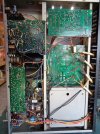
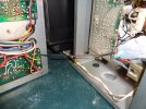
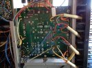
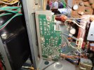
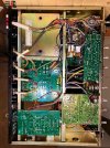
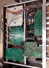
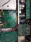
Today I removed the faceplate, tuner tray, and eventually the bottom cover. That bottom cover was quite filthy, but surprisingly, the PCB’s looked like someone had cleaned them recently.

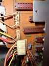
First item of concern for me is the F-2654 / 55 Dolby boards. I didn’t get brave enough to remove them from the chassis. (I don’t know how yet). What I see confuses me a bit. From all the videos and photos I’ve seen lately, I expected to find 4 jumpers under the F-2655 protected with clear tubing, but this is what’s in my receiver.
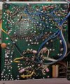
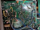
F-2655B.jpgDSC00635.JPG

Out of curiosity I checked eBay for any listings, and found two. But they are different. One of them appears similar to mine, but the connections don’t look the same.

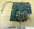
ebay2655-1.jpgebay2655-2.jpg

Production change or what? Can someone explain this to me please?

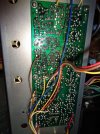
Some of the soldering on my board look pretty bad, the grey ribbon cables are not stock, and I still don’t know what’s between the two boards.
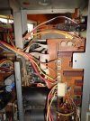
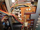
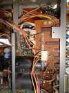
DSC00646.JPGDSC00655.JPGDSC00656.JPG
 
When I looked again at the tuner tray I thought I could actually isolate it and completely get it out of the way, but I was wrong because of one little black (ground?) wire.

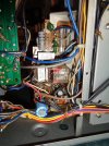
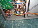
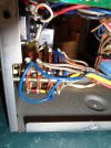
I pulled red and a black single wires out of the tuner board, a yellow wire and a white 2 wire plug from near the Front End, and then 3 Molex type plugs from the Eq. Board. But when I started removing the tray, there was still a 5 wire plug connected to the F-2654 switch board, and a single black wire soldered to the bottom of the tuner Pwr. Supply board. I traced the other end to the back panel about mid point of the heatsink.

That black wire had very little slack, so I ended up putting it partially back together, flipping it with the heavy end face down, and then “swinging” the tray out like I’ve seen other people do. If that one darn wire had some sort of disconnect, people would be able to remove the tray and put it anywhere they like.

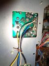
While I was taking the faceplate off, I also noticed that one of the 2 thin brass jam nuts was missing. They go between the knob and the faceplate at the Dolby Function and the Treble Adjust. The thread measures .350”, which is not quite 9mm. That’s an oddball I thought, did Sansui use proprietary threads on their equipment? An hour later I was rummaging through my electrical junk stash to see if I had some spade connectors for that little black wire, and found a little coax connector part that had a thin brass nut on one of the threaded ends. The hex was ½” instead of 12mm like the Sansui nut, but the threads measured the same and matched nicely. (and she’ll still complain that I’m a pack rat). :b

DSC00634.JPGDSC00641.JPGDSC00642.JPGDSC00643.JPG
 
These are some extra pictures I took with the tuner tray and the cover removed. Sorry about all the large photos I posted earlier when I could have just attached files instead.
 

Attachments

  • DSC00654.JPG
    DSC00654.JPG
    157.3 KB · Views: 13
  • DSC00637.JPG
    DSC00637.JPG
    104.6 KB · Views: 14
  • DSC00639.JPG
    DSC00639.JPG
    109.5 KB · Views: 12
  • DSC00638.JPG
    DSC00638.JPG
    110.6 KB · Views: 12
  • DSC00640.JPG
    DSC00640.JPG
    169.3 KB · Views: 9
  • DSC00644.JPG
    DSC00644.JPG
    176.1 KB · Views: 10
  • DSC00645.JPG
    DSC00645.JPG
    167 KB · Views: 9
  • DSC00647.JPG
    DSC00647.JPG
    155.5 KB · Views: 11
  • DSC00648.JPG
    DSC00648.JPG
    118.7 KB · Views: 10
  • DSC00650.JPG
    DSC00650.JPG
    121 KB · Views: 16
The easiest solution to the Dolby board issue is to completely disconnect it. It involves removing the ribbon cable cto the switch board completely, adding 4 jumpers on the switch board to the points where the ribbon originally connected, and moving the two shielded cables from the Dolby board to the switch board. The process is described in this post (see #34), and it does work perfectly.

 
The easiest solution to the Dolby board issue is to completely disconnect it.
I'm familiar with that Dolby Bypass thread and have read parts of it multiple times. I also agree with most of the opinions that it would be best to repair the board(s) if possible. (just for resale value).

What I'm curious about now is why I'm finding different examples of what the foil side of the F-2655 look like. Do you know if the pictures above with all the blue jumper wires were the original OEM condition of the boards, which were later altered during the production run?
 
I suspect the blue jumpers were an attempt to bypass some foils on the top of the board that had become disconnected due to open feedthroughs.
 
I suspect the blue jumpers were an attempt to bypass some foils on the top of the board that had become disconnected due to open feedthroughs.
I had asked a similar question on another thread, and another AK member agrees....

"My best guess is those jumpers are not original and are an attempt to bypass bad pass throughs. A fix like that may have been known through the dealer network."
(- Pete)

I'm gonna think on this for a while as I do some actually needed chores. At my current skill level, being able to do the Dolby bypass would probably have a better chance of success than all the work of repairing or replacing that F-2655 board.
 
I wonder if doing the Dolby bypass that retains the tape monitors would actually increase the value of the unit more than repairing the Dolby PCB. Once the board is bypassed, there is no chance that it would ever cause issues in the future due to intermittent switch etc. I seriously doubt anyone uses the Dolby circuit in the DB receivers, as there is no more Dolby FM, and most all cassette decks have a better Dolby circuit built in. I suppose it could be used with an old reel to reel that doesn't have Dolby built in, but I doubt that happens often. I typically just do the bypass for units I see in my shop now. I have not reworked the feedthroughs for a long time.
 
I wonder if doing the Dolby bypass that retains the tape monitors would actually increase the value of the unit more than repairing the Dolby PCB.
That would depend on the person buying it? I've only seen one 9090DB up for auction where the seller stated clearly that the Dolby circuit had been bypassed as a selling point, and he was asking top dollar. (I didn't track the auction).

At this point though, you're right. It's kinda like having a special TV with a button that when you press it, you switch to B&W and the sound is replaced by captions you have to read.... just like the early "moving pictures". Then one day you push that special button and the feature doesn't work as before. Are you gonna take it to the shop to fix something nobody would use anyway?
 
There are instructions for properly bypassing the Dolby board. This one was done improperly, that's why the tape functions don't work.
I've suspected that a botched bypass caused the tape function problem before Dr.Audio confirmed this. I'm also thinking the botched bypass has something to do with the Tone controls not working properly. I want to redo the bypass, but first I need help identifying two black wires that I believe were also added along with the blue and yellow jumpers.

One of the black wires runs from a wide trace on the Dolby board where the diagram doesn’t even show a thru hole, to another wide trace on the Tone board where there might be a thru hole near C53. (the service manual doesn’t show all the thru holes clearly). Is this a ground to ground connection between the two boards? (that would be weird).

The other black wire also runs from the Dolby board near the 3rd (of 36) ribbon cable holes (maybe even the riveted via), from the top when viewing the diagram, going to the Equalizer board at the (07) 4 Pin Assy. (I'd have to pop the bottom cover again to see exactly where the connection on the Dolby board is).

Both of these wires need to go before I can remove the Dolby board, so if anyone can tell me what they are, and if they need to be replaced after the bypass, that’s half a beer for you!

Wolf
 

Attachments

  • DSC00634.JPG
    DSC00634.JPG
    187.9 KB · Views: 11
The only things that need to take place to bypass the Dolby board completely (and retain the tape monitors), is to completely disconnect the ribbons from the switch board, move the two shielded wires from the bottom of the Dolby to the appropriate locations on the switch board, and add the jumpers to the ribbon connector locations on the switch board. All of the other connections to the Dolby board are irrelevant, and can be disconnected
 
All (of the other) connections to the Dolby board are irrelevant, and can be disconnected.
Thanks for the confirmation Bob.... I was waiting for someone that knows better to spell it out. BUT, you didn't describe what those added jumpers are there for, so NO 1/2 beer for you! :b
 
All of the other connections to the Dolby board are irrelevant, and can be disconnected.
Turns out it's not quite that simple with this unit Bob. Before snipping wires I decided to do some more looking around for bottom views of 9090DB's with the cover removed to confirm I can discard those two mysterious black wires. I was only able to find 3 images online. All 3 images show a long black wire also connected to the Tone board at the same connection point as mine, but only one might be connected to the Dolby board. The other two images show that they go somewhere else. From the photo's, I can't tell where, but they don't seem consistent either. So if I snip this wire off of the Dolby board, I'll have a straggler wire that should be connected back to somewhere unknown (at the moment).

None of these images show the other black wire I have (or any wire) connected to the Equalizer board. So I'm guessing I can remove that one completely and not worry about it?

Strangely, two of the images also show a light grey jumper wire on the Equalizer board. Both complete the same connection. The 3rd image (as with my receiver) do not have this added jumper.

Looks like there are plenty of 9090DB's out there that have been modified, and I have probably only spotted a few of the differences so far.
 

Attachments

  • sansui-9090db bottom 03.jpg
    sansui-9090db bottom 03.jpg
    137.1 KB · Views: 10
  • sansui-9090db bottom 01.jpg
    sansui-9090db bottom 01.jpg
    101.4 KB · Views: 10
  • sansui-9090db bottom 02.jpg
    sansui-9090db bottom 02.jpg
    120.8 KB · Views: 10
Well this is a bummer.... I was hoping someone familiar with the 9090DB would chime in and identify this mystery black wire for me. Every image I can find with the bottom cover removed all show this connected to the same place on the Tone board, but where the other end should be connected to is still unknown. I'm no good at reading schematics and trying to figure it out, so if you can help, that would be great.

Wolf
sansui-9090db bottom 03.jpg
 
Well this is a bummer.... I was hoping someone familiar with the 9090DB would chime in and identify this mystery black wire for me. Every image I can find with the bottom cover removed all show this connected to the same place on the Tone board, but where the other end should be connected to is still unknown. I'm no good at reading schematics and trying to figure it out, so if you can help, that would be great.

Wolf
View attachment 3776353

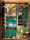
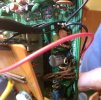
From what I can tell looking how it runs across the front then over the Dolby board, I think it connects to a pin that has that other black wire going to the same place. Look at the first pic of yours I copied. The red arrows point to your wire and another black wire I believe connect to the same pin on top of the Dolby board (yellow arrow).

Second pic shows pin with the two black wires going to it.

sansui-9090db bottom 03.jpg

TJ49a.jpg
 
From what I can tell looking how it runs across the front then over the Dolby board, I think it connects to a pin that has that other black wire going to the same place.
I think you've got it.... now that I go back to the images I left on post #36, fuzzy as they may be, it's likely that all 3 machines have that wire running to the Dolby board same location. Are these ground wires? When I bypass the Dolby, should I snip the wire off the Dolby and connect it to the chassis?

The Service Manual shows that wire connected to the wide trace near C33.

Tone Board.jpg
 
Back
Top Bottom