• The move to the new server is done. There are some software and database maintenance updates in process. This has us passing the hat around to help out. We appreciate any donations. Seriously, even a dollar helps. The payment page may be found here - https://www.audiokarma.org/support.html

Update on new EMIT/EMIM Diaphragms

Status
Not open for further replies.
Here's a pretty clear picture of what the tape strips look like. You can see the vertical stripes where they overlap on the film.

I see, thanks! Guess I was just looking at the part of the racetrack that's on the other side of the diaphragm!

 
I plan to do this tonight while I'm pulling the EMIMs in order to change out the old diaphragms and test the felt stuffing.

Sorry guys, I have been strongly warned NOT to directly connect a ribbon to an amp, as the slightest DC offset can kill the ribbon. I really don't want to buy a new set so soon, so we'll have to go with the crossover results.
 
To help clear the tape thing up, it's not just the tape strip down the center. Those EMIMs have vertical strips of "scotch" tape across the entire diaphragm, from one side to the other. It was their means of damping resonances. Later EMIMs do not have tape strips, but have a layer of another material sprayed on them to do the same thing. I had to remove the layer/tape in order to do the analysis of the films themselves. In either case, it adds mass, which slows the diaphragms down. For what it's worth, Graz uses a completely different means of damping, which I think is quite clever.

I'm not claiming to be a blind tester, and I'm just giving my impressions, take them or leave them as you wish, no offense taken either way. I'm sure the transient response could be measured by someone with the right equipment to take time domain measurements, but that's not me. I'm already spending way too much time on this at the expense of work and family. My goal was to get someone to make us replacement diaphragms; we are there now, so the goal has been reached. I feel they are also an improvement, but the only way for you to know is to try them out yourself, on your systems.

Is it possible to get Graz top do these measurements. I think listening to the product is the final test but some objective testing needs to be done to see what the actual differences between the two are.

I would be interested to see some nearfield testing with the diaphragm mounted on a large baffle as well as some impedance measurements which would tell us where the resonance is. Impulse measurement would be nice as well.

regards
 
All I have to say is THANK YOU Graz we now have the means to repair our EMIMS.

As an owner of RS IIBs and RS 4.5s it is a a blessing. Can't wait for the EMITs

BTW I have a few original used EMITs diaphragms. Got these when I was a Sales Rep.

Just my .02c

Now back to the regularly scheduled program
 
Do the EMIMs look better to you guys than I think they look? It's great that they produce sharper transients... but the overall frequency response? Graz's certainly looks much better than the stock EMIMs.

What do you do with the 8db valley before before the EMITs take over?

What are the steps in Hz on the graph between 100 and 1k, and 10k?

I'm sorry, fellas. Discovering the apparent weaknesses of the EMIM after all this time is a little disheartening.

Before we all start committing speaker Hari-Kiri, remember that the measurements I posted are in-room, with lots of stuff around (tables, chairs, other speaker cabinets, etc.). They were intended to show that the new diaphragms are covering the same frequency response range as the stock ones, not for uber-close inspection of all the squiggles in the plots. I should be able to re-check those measurements later in the week, once I put the new diaphragms in the other speaker - I will then be checking the EMIMs with felt inside to the ones without. I will try to clear away all possible reflection sources to get as clean a measurement as possible over the midrange.

Then it's time to just enjoy them!
 
When I make one of my own speakers, I build a prototype from a theory, listen to the result, and hunt any anomalies with measuring equipment - in that order.

Measurements have to be meaningful - and in the case of the EMIM's the equation has far too many variables. An "in situ" comparative measurement is probably about as meaningful as it gets as such a "test" can say one thing, and one thing ONLY. That is, a random sample of 8 dipolar drive units approximately 3 decades old produces a similar response reading in an unknown mic, rta software, sound card, mounted in a similar baffle, running through an unknown amp into unknown xover parts! Change any of the above, even the stock drive unit sample from the same group and the results change! And it must be said that despite the similarity of units' plots - there is an undeniable difference in sound quality as the newer unit sounds more immediate.

Transition profiles of bass drivers through to midrange drivers has been raised, and at the best of times crossing a cone to a ribbon is something that has variable success. As Infinity built it's (successful) range of speakers on several configurations of relatively few "building block" drivers my task becomes harder. When I make a speaker design I make custom ribbons to work together, and the WHOLE is firmly in mind for this. In blending a MR from a bass the xover, mass, size and a few other variables make the best of a bad situation. With vintage infinity drivers few of your bass cones will have the original roll fitted, and all will be in varying stated of aging, all factors that change the woofer's shaping.

If I were to plot a response of a dipole EMIM here it would tell you a result of a similar collection of variables I had deemed acceptable for the test, and if any of you ran the same sweeps in your own speakers through your own xovers in your own rooms will likely get different results! Shoving a mic up to a multi-aperture dipole driver on one side tells little of how it will sound in a real system!

Perhaps some of you will understand why I haven't posted plots from the driver now!

I understand that you guys want ribbons - but also understand i am ulikely to be able to please everybody. Even a "son of a founder" doing work for a well established audio brand (think of Koetsu) has their detractors - me, i'm nothing! If you go back to the 80's Apogee was one of the "enemies"!!!!

***

A word of warning to people taking their drivers apart to play - DC is a killer of ribbons! Many/most amps put this out at the terminals in various quantities, and this can change from turn-on to in-operation to turn-off. When your EMIM/EMITs are in the whole speaker they are protected from this by the xover, take one out of line for a direct connection and you may find out the hard way how much DC your amp puts out!!! "Testers" are advised to put a high value cap inline, though of course this will change the results ;)

Lastly - FORUMS. I already write a lot and read all of the Apogee forum, adding AK to that leaves little time to do work! I will not have time to be in here often, and "pm's" are best handled through my ribbon email address;-

info@apogeeribbons.com


Take care - Graz
 
Well, things relatively certain are the Graz EMIMs perform at least similarly, if not better than the originals with somewhat improved frequency and transient response, the quality of the diaphragm is superior, and the benefit of brand spankin new instead of aged used or NOS. And no friggin Scotch tape dampening. At the bottom line EMIM replacements are about to be available with no thanks to Infinity when most of us probably thought we'd never see them. Thank you Graz! You are our hero!

Let me shift gears here for a second...

Someone dropped this free test CD (on the web) under my nose today.

http://binkster.net/extras.shtml#cd
 
It's easy to do with nearfield testing. Set the mic right up near the speaker diaphragm and use a program such as spectra lab etc to do a frequency sweep ;)

181c1fc8.jpg

Nearfield testing of a woofer in my RS-4.5 this morning with an HP signal generator and the Radio Shack meter yielded some interesting results. While there were some minor dips, the more compelling result was 2 large peaks, each at least 6 dB in amplitude, one at around 80 Hz and the other at 100 Hz. Not what I expected but these must be factored into any equalization intended to address a suckout in the low end of this speaker system.
 
Nearfield testing of a woofer in my RS-4.5 this morning with an HP signal generator and the Radio Shack meter yielded some interesting results. While there were some minor dips, the more compelling result was 2 large peaks, each at least 6 dB in amplitude, one at around 80 Hz and the other at 100 Hz. Not what I expected but these must be factored into any equalization intended to address a suckout in the low end of this speaker system.

That sounds like a fault of some kind. Do both speakers measure the same ??

From memory when I did the tests on my speakers the dip at around 60Hz was only 2 dB down from the 2 peaks either side of that frequency and not at 80Hz and 100Hz.

regards
 
That sounds like a fault of some kind. Do both speakers measure the same ??

From memory when I did the tests on my speakers the dip at around 60Hz was only 2 dB down from the 2 peaks either side of that frequency and not at 80Hz and 100Hz.

regards

Yes, both the same. Who knows maybe the caps have aged in the crossover? One thing I have not done yet is to completely remove the crossover boards and check the seal of the cabinets where the woofer wiring is routed; it is possible this seal may have have deteriorated (as yours did) and is causing some anomaly in low frequency response.
 
Last edited:
BTW Rabbit, in looking at the picture of your sweep test setup, I notice that the surrounds on your RS4.5s appear to be rubber rather than foam. Is this just the camera angle/lighting? My refoamed 4.5 woofers use a light gray replacement foam surround.
 
Yes, both the same. Who knows maybe the caps have aged in the crossover? One thing I have not done yet is to completely remove the crossover boards and check the seal of the cabinets where the woofer wiring is routed; it is possible this seal may have have deteriorated (as yours did) and is causing some anomoly in low frequency response.

Yes this is quite possible so worth checking.

3 of my woofers have a rubber surround and one has a foam surround. Foam is ok as long as it's a closed cell construction but rubber lasts a lot longer ;)

regards
 
Yes this is quite possible so worth checking.

3 of my woofers have a rubber surround and one has a foam surround. Foam is ok as long as it's a closed cell construction but rubber lasts a lot longer ;)

regards

adding rubber where foam was originally has been known to change the sound in some instances. i think that must indeed be taken into consideration in these response plots.
 
adding rubber where foam was originally has been known to change the sound in some instances. i think that must indeed be taken into consideration in these response plots.

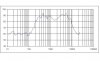
much less likely in a sealed enclosure where the the box compliance dominates over both the suspension and spider compliance.

The major issue effecting the RS-4.5 is when the foam rubber under the crossovers perishes and courses air leakage thus acting like a vented box :(

regards
 
TrueRTA Plots of Graz EMIMs

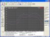
I bought the TrueRTA software (1/24th Octave version) so I could make some better measurements for you guys (and me!). Below is a 1/6 octave pink noise frequency response graph of all three of the the Graz-ed EMIMs in my RS2b, through the crossover, with woofers and tweeters disconnected, at 1 meter distance, using the RS meter as a microphone (it's pretty accurate through the midrange region).

As you can see, it looks very similar to what I created earlier using the RS SPL Meter and a test tone CD, but with better resolution. There is still a ~8dB dip centered around 1700Hz. The 1/24th octave plot is similar, but with a lot more short-term structure - I'll be using that when I do the critical analyses of felt lined vs non-felt lined shells, different thickness spacers between EMIM shell and diaphragm, etc.


Edit: It is apparent in later graphs (below in this thread) that the 1 meter distance is causing the choppy response, since the three EMIM drivers do not have enough room to integrate properly. Later plots from further back (especially from the listening position) illustrate this clearly.


.
 

Attachments

  • Graz EMIM 6th Octave.JPG
    Graz EMIM 6th Octave.JPG
    39.5 KB · Views: 44
Last edited:
I had a suspicion that the dip in response around 1700Hz may have been caused by my crossover, rather than by the EMIMs, so I plotted just the Low EMIMs overlayed with the High EMIM. See the attachment below. It certainly looks like the crossover is to blame - I built it according to the schematic (which was verified by inspecting my old crossover parts), but it looks like I need to roll the high EMIM in a bit lower than it is currently. I am using a 22uF Mundorf Supreme cap as the high-pass (measures 22.4uF) whereas the schematic calls for 23uF.

I will try adding some additional capacitance to the high-pass on the high EMIM to lower the x-over point a bit. Time to experiment - perhaps another Mundorf Supreme? Perhaps one of those nice Russian K40Y-9 PIO caps I picked up from e-bay?
 

Attachments

  • Graz EMIMs Overlay (original X-over).JPG
    Graz EMIMs Overlay (original X-over).JPG
    52.2 KB · Views: 34
Effect of High Midrange Pot in RS2b Crossover

Before I started to play with the high-pass caps, I decided to check out what effect the high mid pot would have on the dip at 1700Hz. It turns out the effect is BIG. See the plot below. The lower trace is with the pot set at the lowest level (highest resistance). The middle trace is with the pot set at the midpoint, and the upper trace is with the pot set at the highest setting (resistance = 0). As can be seen, adjusting the pot to 0 resistance is able to eliminate most of the dip.

Once I put the equalizer back in the circuit, it may extend the low EMIM response enough to eliminate the dip completely, or I may want to put a little more capacitance in the high mid high pass filter. In any case, the dip has been reduced to only ~4dB, which may be inaudible as is.
 

Attachments

  • EMIM Pot Effect.jpg
    EMIM Pot Effect.jpg
    109.9 KB · Views: 46
After optimizing the resistance of the pot (0 ohms worked best), I checked out the effect of microphone distance from the speaker. The readings above were taken 1 meter from the center of the EMIMs, so I compared that with 2 meters (see attached graph; 1 meter is the upper line, 2 meters the lower - I added a 6 dB offset to the top line for clarity of viewing). Realistically, 2 meters is about as close as anyone will sit - In my room I'm about 11 feet away.

As you can see, at 2 meters the low and high EMIMs blend more seamlessly, and the dip at 1700Hz is pretty much gone. I don't think I'll be needing to add any capacitance after all!

All in all, the response of the Graz-ed EMIMs looks flat and smooth. Very nice!
 

Attachments

  • EMIM Response 1 vs 2 meters.JPG
    EMIM Response 1 vs 2 meters.JPG
    115.5 KB · Views: 35
Just a note on the input mv levels in the above graphs. After making these measurements, I noticed that the mv input levels displayed were quite high, so I went back and checked the last two sets of measurements with the generator amplitude set lower and an input level of 700mv. The resulting graphs looked the same as those done at the higher levels, so I have left those posted.
 
Finally, here's a full range 1/6 octave FR Plot of the RS2b, without the LF equalizer in line, using a mic correction file for the RS analog SPL meter which I obtained from the "TrueRTA for Dummies" thread on the AVS forum. The SPL meter was positioned 2 meters from the speaker at approximately ear height. Both the high mid and low tweeter pots are at the fully high setting, the high tweeter pot is in about the middle of its range. This speaker has the new Graz diaphragms installed in both the high and low midrange EMIMs

Considering this is in-room response, the plot is pretty flat in all regions, and actually looks a lot like the plot shown on the Infinity Classics.de website for the RSIIa, without equalization. Both plots show the slow slope downward from low to high frequencies that seems to be characteristic of these speakers. There is also no sign of a mid-bass suckout between the EMIMs and the woofers, even without the LF equalizer in place, so those who biamp and bypass the LF EQ for the mids on up should be fine as far as integration of bass and mids is concerned. You can also see very clearly why these speakers use a LF EQ - the bass drops off pretty sharply below 50Hz without it, and the mid-bass is too pronounced; the EQ is designed to address both of these issues. Right now I'm in the middle of changing the RCA jacks in the LF EQ to gold over copper DHT Labs jacks, and adding in a few more of the excellent Texas Components TX2575 resistors in place of the PRPs, so I won't be able to measure the response with the EQ in line until I finish that (probably in the next 2 or 3 days).


.
 

Attachments

  • Full Range RS2b FR Plot, HM, LT set to high.JPG
    Full Range RS2b FR Plot, HM, LT set to high.JPG
    109.5 KB · Views: 47
Last edited:
Status
Not open for further replies.
Back
Top Bottom