
• The move to the new server is done. There are some software and database maintenance updates in process. This has us passing the hat around to help out. We appreciate any donations. Seriously, even a dollar helps. The payment page may be found here - https://www.audiokarma.org/support.html

uxcell Film Capacitor can't find any info

I was trying to help the OP with a simple way of taming the brightness inherent with swapping from the horrible black-bodied, red-ended ALCAP or COLLINS capacitors to new film capacitors due to large differences in ESR. The typical values have been measured before on this forum and others.

ESR isn't the problem.

Electrolytics have poor performance for frequencies above 1k Hz even when new, and the capacitance reduces with frequency. Beyond that, electrolytics degrade with age and cease to function as capacitors. Many even short out. At best an electrolytic rectifies the signal, causing distortion.

A brand-new, low ESR NPE will not have the same sound of a PP film, particularly given that the capacitance will be an unexpected value when the frequency is above 1k Hz. Electrolytics are best used for power supply filtering, not signal path uses.

Yes, I should have known better and should have provided details of a proper L-Pad or T-Pad. Sorry I didn't have time to go into this kind of detail - I was posting from my phone at the time.

An L-pad is the easy and proper fix to balance tweeters against other drivers, and that's the easiest and best solution. Adding impedance to the path will shift crossover points, and a few hundred Hz in the midrange is going to be noticeable, given that humans best hear in the midrange.

What happened instead of an L-pad being added is the OP added not the 1 Ω you suggested, which is problematic enough, but twice that value: 2 Ω. That was even worse than your suggestion, as the crossover point has now been downwards shifted by 20%. Using the example I above set forth, the crossover point is now 1,989 Hz instead of 2,487 Hz. That's a downwards shift of 500 Hz!

Now, if that was shift was solely restricted to the tweeter it now overlaps the midrange by 500 Hz, and it is only the reduction in efficiency which doesn't make this "solution" sound even worse, particularly given the comb artifacts from substantial driver overlap.

Electrical engineering is governed by physics which is expressed as mathematics. The formulas do not lie. Anyone may easily calculate the crossover point given the alterations in impedance. Crossovers function as electrical filters and the formulas are well known, easily computed, and not hard to understand. Ad hoc solutions are not desirable.

OP: upgrade the NPEs to PP film, add an L-pad, balance tweeter, done.
 
62B5298E-101A-44F8-A4E3-681C04AC49C2.jpeg

For the most part, this is an excellent discussion....

So would it look something like this?


VR,
Andy
 
View attachment 1636419

For the most part, this is an excellent discussion....

So would it look something like this?

Nope. That circuit uses a rheostat to add variable resistance in series with the driver. All wrong. The crossover point will shift all over the map. In terms of effect it is no different than placing a fixed resistance in series.

The L-pad must be placed across the driver because it is a current shunt. An L-pad has a series resistance and a shunt resistance. The two inversely track to present, in conjunction with the driver, a constant resistance to the filter so the crossover point does not change. (The driver, to contrast, does not see a constant resistance, but that does not matter for this application. A T-pad has constant resistance on both sides.)

Search for L-pad and tweeter using Google and you'll see how to hook it up.

Also, fuses in the signal path may add significant distortion, particularly when larger amounts of power are in play. I've elsewhere posted some data on the effects taken from learned tomes, not audiophool dogma.
 
I like you telling me in easy terms what to get. THis is all new to me and I love any and all help., thank you guys.

OP
 
Nope. That circuit uses a rheostat to add variable resistance in series with the driver. All wrong. The crossover point will shift all over the map. In terms of effect it is no different than placing a fixed resistance in series.

The L-pad must be placed across the driver because it is a current shunt. An L-pad has a series resistance and a shunt resistance. The two inversely track to present, in conjunction with the driver, a constant resistance to the filter so the crossover point does not change. (The driver, to contrast, does not see a constant resistance, but that does not matter for this application. A T-pad has constant resistance on both sides.)

Search for L-pad and tweeter using Google and you'll see how to hook it up.

Also, fuses in the signal path may add significant distortion, particularly when larger amounts of power are in play. I've elsewhere posted some data on the effects taken from learned tomes, not audiophool dogma.


Was trying to get a visual so thanks for explaining, and understand it’s not representative of your recommendations....

But all wrong? That’s a common tweeter crossover design from Infinity for more than one series of their speakers.

If it’s all wrong, then it seems to be a “ very good wrong” ;-)

VR,
Andy
 
But all wrong? That’s a common tweeter crossover design from Infinity for more than one series of their speakers. If it’s all wrong, then it seems to be a “ very good wrong” ;-)

Yes, wrong.

As I set forth in gory detail in No. 59, a filter's corner frequency (fc) depends upon the resistance:
The formulas are basic physics and basic electrical engineering, and are undisputed. Well, a flat-earther might not believe them, but I can't help that.

Use the formulas I above provided for the corner frequency and calculate the difference in fc for 8 Ω, 9 Ω, 10 Ω, etc. which would be obtained my increasing the potentiometer's value. Provided no other parameter changes, the higher the resistance, the lower the crossover point.

You must either (a) accept the formulas set forth as true and accurate and understand the effects as true and accurate or (b) invent your own laws of physics and set forth an explanation of same. I can't fix an unwillingness to accept physics.

The designer at Infinity may have wanted to permit variable overlap of tweeter and midrange to boost the tweeter's output at the low end of its range. That suggest a poor, read "lower manufacturing cost", choice for a tweeter. Varying the resistance has the effects I described and showed via math.

An L-pad contains two potentiometers and consequently costs more than a simple resistor or a single potentiometer. If no need existed to use an L-pad because a series resistor or series potentiometer had an identical effect, then the entirety of speaker designers who understand the effects of changing the tweeter's resistance upon fc, and consequently used a constant-resistance L-pad to blend the drivers, would, of necessity, be incompetent. Plus, physics and electrical engineering would need entirely new laws and formulas, which would be a great boon for graduate students to research and professors to publish.

One or the other must be true. The formulas I posted must either be correct or incorrect. Both cannot be simultaneously true.

I've explained why an L-pad is superior to series resistance and the effects upon fc from altering the resistance of the tweeter without otherwise altering the associated components. You may perform the calculations for yourself, believe or disbelieve the results, and accordingly take your own counsel.
 
Last edited:
Certainly respect your knowledge, humbly acknowledge it’s beyond mine on this subject but Infinity design/production results are not in question, they work well....

Believe you’re dealing with in-vitro vs in-vivo, ;-)

One could say—Infinity’s results “speak” for themselves LOL


VR
Andy
 
Certainly respect your knowledge, humbly acknowledge it’s beyond mine on this subject but Infinity design/production results are not in question, they work well....

Believe you’re dealing with in-vitro vs in-vivo, ;-)

One could say—Infinity’s results “speak” for themselves LOL

You're actually saying that:
(a) You lack any understanding of how filters actually work, and thus cannot explain why the formulas as above set forth do not apply;
(b) Calculated results of universally accepted filter formulas are somehow "different" than the results obtained from actual crossovers;
(c) Crossovers should be designed in ad hoc ways with variable impedance until it sounds "good".​

I suggest reading Vance Dickison's Loudspeaker Design Cookbook. It will explain the issues and educate you that the resistance component of a filter — it is, after all, a charging circuit built using combinations of capacitors or inductors, or both— controls the crossover point. Filters are not magick, and magickal thinking won't change the crossover points.

In the meantime, the OP can best solve the problem using an L-pad as this will not shift the crossover points by varying the resistance presented to the filter.
 
Nope,
You're actually saying that:
(a) You lack any understanding of how filters actually work, and thus cannot explain why the formulas as above set forth do not apply;
(b) Calculated results of universally accepted filter formulas are somehow "different" than the results obtained from actual crossovers;
(c) Crossovers should be designed in ad hoc ways with variable impedance until it sounds "good".​

I suggest reading Vance Dickison's Loudspeaker Design Cookbook. It will explain the issues and educate you that the resistance component of a filter — it is, after all, a charging circuit built using combinations of capacitors or inductors, or both— controls the crossover point. Filters are not magick, and magickal thinking won't change the crossover points.

In the meantime, the OP can best solve the problem using an L-pad as this will not shift the crossover points by varying the resistance presented to the filter.

Nope, never tried to put words in your mouth so please don’t put the in mine...

Also never question the validity of your recommendation. I’m sure it will work.

All I questioned was your dogmatic statement that Infinity’s designs were “wrong”

You could have said that, my understanding/design is better, and I would have accepted that as a possibility, don’t know you, you may design for the top rated speaker manufacturer of the day.

But given Infinity’s real world results, saying that they were flat out wrong in their design is just not a plausible concept.

At one time Physics said, mathematically Bumblebee’s can’t fly, that their weight couldn’t be supported by their wings, of course everyone knew they could fly. It was their conception that was wrong, not the Bumblebees design.

All I’m saying is that Infinity’s design worked/works, it was proven in the market, (sales) it’s continual success is evident within our hobby, (buying/using vintage speakers).

To say it’s wrong is just, well, wrong.

To say it could be improved, that’s even questionable, most people like them with the same components they came with.

To say you can design something better, hey that’s possible!


Really, other than your Infinity was wrong statement, you have my Highest Regards,
Andy
 
You could have said that, my understanding/design is better, and I would have accepted that as a possibility, don’t know you, you may design for the top rated speaker manufacturer of the day.

It is not about my "understanding" or your "understanding". This is not an opinion based upon experience. All that matters is the results from the standard filter formulas I set forth. You may use the calculations or do your own research to verify the accuracy of same. Muddying the water merely confuses the OP, particularly when you have admitted you do not understand filter mathematics.

But given Infinity’s real world results, saying that they were flat out wrong in their design is just not a plausible concept.

I presented a cogent and plausible argument as to why the overlap might be present in that specific speaker.

Relying upon such overlap as a general design concept, is, however, severely flawed as it creates comb artifacts and humps in the response. This does NOT suit the OP's needs to balance the tweeter against the midrange and woofer.

At one time Physics said, mathematically Bumblebee’s can’t fly, that their weight couldn’t be supported by their wings, of course everyone knew they could fly. It was their conception that was wrong, not the Bumblebees design.

Sigh.

We are talking about filters, not insects.

That myth, by the way, is based upon a severe distortion of a single off-handed statement by the entomologist August Magnan in the early 1930s that bee flight would be impossible if the bee solely flapped its wings, so something else was at work. But, as we know, bees do not fly like birds. It is oft-repeated nonsense which is used to discredit physics which has amply explained how and why bees fly. Bee flight combines a very fast up/down wing-beat frequency with short wing strokes and rapid wing rotation/reversal during each stroke to create vortices. Bee flight is quite complex, but is well understood.

Physics has adequately explained bee flight many, many decades ago. Using a statement from nearly 90 years ago as proof that physics doesn't know everything is silly. At one point all chemistry was four elements: earth, air, fire, and water. You may as well point to that to support your contention that the standard filter and crossover formulas are erroneous.

But this has nothing to do with filters, other than to posit magick which "science" cannot explain. That's nonsense. Filter formulas work and are accepted as true.

All I’m saying is that Infinity’s design worked/works, it was proven in the market, (sales) it’s continual success is evident within our hobby, (buying/using vintage speakers).

To say it’s wrong is just, well, wrong.

To say it could be improved, that’s even questionable, most people like them with the same components they came with.

To say you can design something better, hey that’s possible!

Really, other than your Infinity was wrong statement, you have my Highest Regards,

If you want to discuss such speakers in another thread, feel free to start one. That discussion has no relevance to the OP's questions.

I clearly answered the OP's questions, adequately explained why adding resistance shifted the crossover point, provided the formulas, and performed enough calculations to demonstrate that the OP's selection of 2 Ω, notably based upon misinformation, had actually moved downwards moved the crossover point by 500 Hz.

Quod Erat Demonstrandum.
 
You obviously misunderstood or didn’t read my post(s) especially the one with the diagram.

And I understand if you don’t get analogies ;-)

I never offer any advice or solutions nor did I question your solution

Only asked if the solution offered looked like a particular technical drawing, (never stated or implied it as a option)

Infinity used that design, or a minor variation thereof, on most 4 ohm EMIT tweeters with outstanding results.

You said it was “All Wrong” that’s the only thing I took/ take issue with.

Infinity’s design is outstanding, may not be perfect, but it’s not “All Wrong”!


Over and Out
 
Infinity used that design, or a minor variation thereof, on most 4 ohm EMIT tweeters with outstanding results.

The total circuit resistance changes as the potentiometer resistance is altered, thereby altering the corner frequency and thus the amount of overlap with the midrange (if three-way) or woofer (if two-way).

The intent of that design is to provide an alterable crossover point. This is an uncommon design goal and one which has no relevance to the OP's question.

You said it was “All Wrong” that’s the only thing I took/ take issue with. Infinity’s design is outstanding, may not be perfect, but it’s not “All Wrong”!

I specifically wrote that a series potentiometer was not the solution to the OP's problem as the variable resistance would shift the crossover point:
Nope. That circuit uses a rheostat to add variable resistance in series with the driver. All wrong. The crossover point will shift all over the map. In terms of effect it is no different than placing a fixed resistance in series.

I stand by that statement as it is true and accurate. If the crossover point is to be shifted, changing the capacitor value is the correct approach as it does not change the volume as frequency changes.
 
Maybe we should all just agree that there is more then one way to design a crossover. If I was the OP in this situation I would stick with the Solen capacitor since it is a good high quality part and add the two resistors needed for an Lpad to bring the tweeter level down a few dB.
 
Maybe we should all just agree that there is more then one way to design a crossover.

You mean the crossover design schools of (a) using well-known and fully accepted formulas and (b) making it up as one goes along because math is hard?

Yeah, those pretty much seem to be the two schools.

If I was the OP in this situation I would stick with the Solen capacitor since it is a good high quality part and add the two resistors needed for an Lpad to bring the tweeter level down a few dB.

Yes, capacitor is fine and may remain.

A variable L-pad is a superior solution to fixed values, as a fixed L-pad would requiring knowing, a priori, the exact amount of attenuation which was needed. This varies depending upon the music, the room characteristics, and the hearing of the listener.

Plus rotating the inductors 90° to avoid coupling.
 
ESR isn't the problem.

Electrolytics have poor performance for frequencies above 1k Hz even when new, and the capacitance reduces with frequency. Beyond that, electrolytics degrade with age and cease to function as capacitors. Many even short out. At best an electrolytic rectifies the signal, causing distortion.

A brand-new, low ESR NPE will not have the same sound of a PP film, particularly given that the capacitance will be an unexpected value when the frequency is above 1k Hz. Electrolytics are best used for power supply filtering, not signal path uses.


An L-pad is the easy and proper fix to balance tweeters against other drivers, and that's the easiest and best solution. Adding impedance to the path will shift crossover points, and a few hundred Hz in the midrange is going to be noticeable, given that humans best hear in the midrange.

What happened instead of an L-pad being added is the OP added not the 1 Ω you suggested, which is problematic enough, but twice that value: 2 Ω. That was even worse than your suggestion, as the crossover point has now been downwards shifted by 20%. Using the example I above set forth, the crossover point is now 1,989 Hz instead of 2,487 Hz. That's a downwards shift of 500 Hz!

Now, if that was shift was solely restricted to the tweeter it now overlaps the midrange by 500 Hz, and it is only the reduction in efficiency which doesn't make this "solution" sound even worse, particularly given the comb artifacts from substantial driver overlap.

Electrical engineering is governed by physics which is expressed as mathematics. The formulas do not lie. Anyone may easily calculate the crossover point given the alterations in impedance. Crossovers function as electrical filters and the formulas are well known, easily computed, and not hard to understand. Ad hoc solutions are not desirable.

OP: upgrade the NPEs to PP film, add an L-pad, balance tweeter, done.
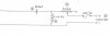
I didn't add a 2ohm I had one here to test and it made a difference.

I did order some 1 ohm parts before this post got way more in-depth.

What would be the best fix for replacing these 2 caps? Just get something similar to what was in there before? I'm not crazy about the idea of adding an L pad.
 
Last edited:
I didn't add a 2ohm I had one here to test and it made a difference. I did order some 1 ohm parts before this post got way more in-depth. What would be the best fix for replacing these 2 caps? Just get something similar to what was in there before? I'm not crazy about the idea of adding an L pad.

Any ordinary polypropylene capacitors — Dayton is the house brand of Parts Express which is what most use — will be fine. I suggest using two smaller values to form the larger value, and then bypassing using a 0.1 µF and a 0.01 µF in parallel with the larger unit. Using smaller values improves the charge distribution and dipole alignment, which matters at higher frequencies such as those driving the tweeter. No need to spend more for a boutique capacitor of dubious value.

The difference you heard in sound was from dropping the volume, but at the expense of moving the crossover point down 500 Hz. That created overlap with the midrange, which was then lessened by the attenuation. That's not a good solution. Because the two drivers are father away than 1/4 wavelength comb artifacts (google it) arise. If you look at the formulas and calculations I posted you'll see why shifting the crossover point happens. It's not a good idea, no matter what others claim.

What's wrong with an L-pad? It acts as a shunt to reduce volume but without changing the crossover point. If you instead add resistance to the circuit the crossover point shifts and you'll need to use a different capacitor to maintain the same point. Otherwise you'll end up with overlap between the tweeter and midrange, creating a hump in the response and causing comb artifacts. The L-pad, to contrast, does not change the crossover point and its effect is purely on volume which is notably fully adjustable. The L-pad truly is the ideal solution. If you find you only need a specific, unchanging value you could, of course, replace it with two resistors of the same resistance, but finding the exact values can be difficult and one often ends up using several resistors to create the necessary values. But why not use the right solution?
 
A pair of sprague atom 8uf 150v Electrolyticc sounds world's worlds better without any burn in yet.

Thanks for the help.guys
 
A pair of sprague atom 8uf 150v Electrolyticc sounds world's worlds better without any burn in yet.

(1) Capacitors don't have burn-in.
(2) Electrolytics in the signal path cause distortion because the unused capacitor rectifies the signal, and PP film is preferred.
 
Back
Top Bottom