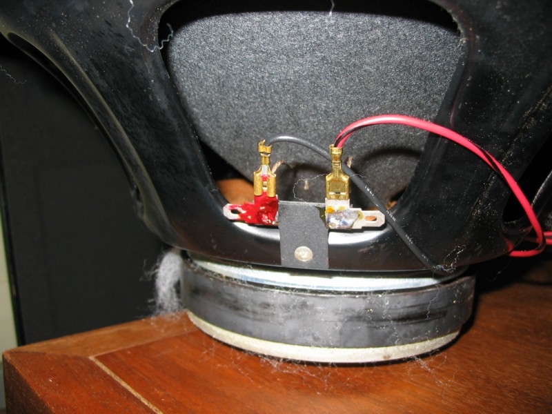
that watkins circuit is more complicated than i realized. RS1b's calculations are right, but they weren't carried to their logical conclusion. the 4-ohm coil has also has a resonance frequency, 373Hz by his math, and the 2-ohm coil (~2.5-ohm DCR, IME) has a rolloff point of 45Hz. confused? i am!
all this time, i had really just been thinking of the two voice coils as having different bandpass filters that, when summed together, gave good flat bass, but there is definitely more going on than just the bandpass.
From
http://groups.google.com/group/rec....=en&q=woofer+group:rec.audio.*+author:watkins
My dual-drive woofer works so:
A second voice coil (vc-2) is wound over the main voice
coil (vc-1) in the woofer, this second coil having a
single layer and very low impedance. Now vc-2 would
normally have an impedance too low for safe operation.
However around fundamental resonance the impedance of
_any_ coil will ~triple. Now we activate vc-2 _ONLY_
in the region of fundamental resonance (around 45 Hz)
and it rises to ~8 ohms or so (being ~2.5 in the
first place) which is safe. This is accomplished with
an LC circuit tuned to 45 HZ and with the Q of the LC
circuit adjusted to provide the response shape and
impedance desired. Please note that the exact value
of vc-2 and the characteristics of the LC circuit give
_COMPLETE_ control of the impedance. The benefit of
the dual-drive may then be taken in extended bass or
higher efficiency in a given size box, or a smaller
box for a given efficiency or bass extension.
---------------------------------------------------
Resonance in a sealed box is the point where the
stored kinetic energy in the moving parts (the mass of the
cone, coil, and ~1/2 the spider and suspension) is equal
to the stored energy in the elasticity of the suspensions
and the air in the enclosure.
----------------------------------------
However, with
dual-drive we simply insert a smaller motor to increase bass
(with a second low-impedance coil), _BUT_ let it work around
resonance _ONLY_, so as to not affect output above resonance.
The see-saw "plank" then can be up on both ends. Bass response
can be adjusted _INDEPENDENT_ from response above resonance.
We can go for efficiency with a larger magnet, or we can minipulate
motor, mass, and enclosure volume, and use dual-drive to achieve
extended bass or a smaller enclosure, as well as deal with the
6 dB response step. (kencat comment-please read all the text before this copied part to fully understand it)
End of Bill Watkins words
A capacitor and an inductor in series with a driver is a simple 1st order bandpass filter. VC1 has a bandpass and VC2 has a bandpass.
cdfac - I think you were right initially. It is just two bandpass filters crossing over the two coils, just like a woofer to a midrange driver.
The trick is to know where the woofer drivers' fundamental resonance is and then design the bandpass filters to have VC2 kick in around this point, and I'm guessing, knock out VC1 or the proper amount of it.
Not sure if all this can adequately be modeled mathematically, but perhaps experimentation is used to fine tune LC values to get the desired response.
rs1b - Aren't those calculations you showed a bit simplifed, and ignoring the electro-mechanical equivalent LCR circuit of the driver mounted in the box? Bill Watkins says the resonance is 45 so the 30Hz is close. Looking to understand this better as well.
Good stuff this is.



 but I find it fun to dig into the technical history of the Quantum line, and I threw that out to see if anyone had more info. You seem to have unearthed a bit of a mystery here.