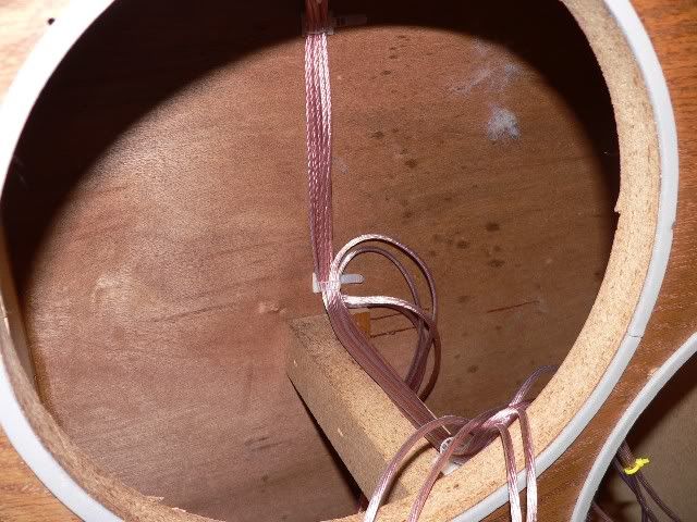
Well, they say a picture is worth 1000 words, but I guess I don't have 1000. I'm not an engineer so the crossover frequencies and bandpass for that particular speaker (mid-bass) are fine with me. So I'm not qualified to comment on the design--I'm not an engineer or speaker designer. But of course it's a rather simple formula for determining the resonant frequency of LC circuits. 1/6.28FC = 6.28FL where F is the frequency, C is capacitance and L is inductance.
Nope don't care who manufactured the parts. I don't know a good electrolytic cap mfgr from a bad one.
BUT, the construction, yes I have a serious problem with that. First of all I would like to see the components mounted on a PCB with traces rather than point-to-point wiring. The cables should be attached to post or else hard wired to a PCB via through holes. The caps should not be stacked on top of each other and held down with glue. They should all be mounted on a PCB and maybe secured with tied wraps. The leads coming off the inductors look hideous and they seem to be touching the case of the inductor. This looks at best like a build up in the research lab rather than a production run. I can't believe this came from the factory this way. This must of been somebodies home brew modification? Replacing parts would be difficult with this "rat's nest".



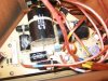
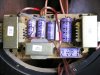


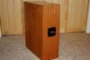

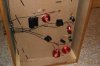


 It's like Infinity got people down at the local tech college to practice their soldering skills by building the crossovers for them