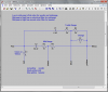
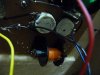
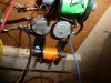
Here is a drawing of the cross over from a W60D that I have acquired as individual parts. I have cabinet of a W60E and that's the rub. There are some differences in mounting the drivers so I haven't created the Frankenspeaker yet.
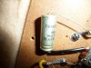
I have drawn the two adjustable resistors (or potentiometers or pots for short) as two resistors. The sum of the two resistors making up the pot is 50 ohms. The capacitor values are those printed on the capacitors. I have not measured the inductors. My second inductor is yellow rather than green.
I too am dubious that all of the drivers are dead. Note from the schematic I posted that all of the drivers in parallel. So if nothing is working, check to see if the binding posts still connect to the wires. All speakers have one lead connected to the minus binding post (yellow wire in my case.)
Notice if the pots are turned to minimum sound level, the corresponding mid-range or tweeter receives no drive voltage because the pot will have a value of 0 ohms between the tap that drives the speaker and the minus binding post. So if the pots are on minimum then neither the mid-range or tweeter will work. Turn the resistors to the maximum sound setting for further testing.
With a simple ohm meter, you can do a lot of testing. Test each speaker with an ohm meter. However, there are a few things you will need to do.
First, before testing switch both pots to the maximum volume position, otherwise, you will read nearly 0 ohms for the mid-range unless you do.
One caution you will not be able to measure the resistance of the tweeter without disconnecting it from the cross over. It is in parallel with an inductor so a simple ohm meter will read nearly 0 ohms unless you disconnect it. I recommend not disconnecting the wire at the tweeter. Instead do it near the cross over or better yet somewhere in the middle of the wire and solder it or use a wire nut to repair the cut. You only need to disconnect one wire for testing.
Also, I think yours may have been re-capped. The main thing to watch out for is the correct value and if electrolytic capacitors where used (that's what yours look like to me) be sure they are non-polarized. Basically if you see a big - in a arrow or + sign near one side, that is not a good.
If the tweeter turns out to not work, check out
http://audiokarma.org/forums/showthread.php?t=139198 for someone who managed to repair one. However since the wire is aluminum, you might want to get some help with this one. It is non trivial to impossible to solder. I managed to destroy one. I have some others that I will probably attempt to repair during one of the upcoming holidays. The failure mode is not them actually burning out from too much power, but the glue corroding the aluminum wire. If you look carefully, you might be able to see a break if they do not work.
++++++
P.S. Although my capacitors are 6 uF and 64 uF, these values (at least the latter) do not seem right. 25 uF would seem closer to the desired value, I'll have to investigate further. Maybe the caps in the cross-over I am examining are not original.
P.P.S. Verified the values with other images on the web, my values are consistent with other posted images.