• The move to the new server is done. There are some software and database maintenance updates in process. This has us passing the hat around to help out. We appreciate any donations. Seriously, even a dollar helps. The payment page may be found here - https://www.audiokarma.org/support.html

Why does Leestereo insist on increasing power supply/decoupling capacitors?

Another example.
I was just now looking at the schematic of the B-2201/2301.
Here is stated for the main filter capacitance: 100V version, 10000uF plus 20000uF ( in parallel ) each channel.
120/240 V version ( international), 2x25000V (in parallel) each channel.
So for the domestic market they went with less capacitance (-40%) and, what you can see more often in the X-balanced 907's and D907F/G Extra and X Decade, one higher value and one lower (with often the same dimensions for half the capacitance).
So here is my curiosity, what other parameters are they considering here.
Clearly they went with maximum capacitance for the international market, knowing that would have value in the US and Europe!
 
Just to add to my last post.
In the alpha series DR, KX, MR Sansui went even more extreme in the au alpha 907 models.
The 607 models would have 2x12000uF shared by two channels. The 907 models have 10500uF for each channel. They could have gone easily with at least 24000uF / channel.
So what is so special about those 5600uF/3900uF capacitors they used that they didn't use the same as in the 607's, two in parallel. This 10500uF is for a channel that should deliver 160 Watt / 8 ohm.
 
I’ve butted my head against this and don’t have an answer either.

Take two almost polar opposites in terms of main capacitance spec, the Sansui 9090 @ 145w with 6800uF capacitors and the Yamaha CR 2020 @ 120w with 18,000uF.

I have both and stock the Sansui definitely had the fatter bottom end and no shortage of dynamics, punchier in fact than the Yamaha with almost 2.5x the power supply capacitance. The sonic signatures remained after I replaced them with 10,000uF and 22,000uF capacitors respectively though there was definite improvement in the bass of both.

The Sansui does have the larger transformer but the Yamaha’s transformer is by no means undersized for the power level.

then there is a pioneer SX980 with 22,000uF that is in between somewhere in terms of sonic signature…

the rough and ready conclusion I’ve come to is that sound of the amp is by it’s design and as long the components used to rebuild/repair meet the specs of the originals ( not very hard to do these days with respect of electrolytic caps, even really cheap ones) then the amp will sound at least as good as it it did when it left the factory; which can’t be a bad thing.

Upgrades and improvements from component that better those original specs are a less clear area for me and I defer to the more experienced, quite possibly with better hearing than I.

in answer to your question then Grispato, they may have made the changes simply because they had component chain challenges and could hear no difference on the sound.
 
in answer to your question then Grispato, they may have made the changes simply because they had component chain challenges and could hear no difference on the sound.
I agree with the statement that when the minimum amount required in capacitance is met with some margin it's up to the circuit design. Still Sansui would give a big margin on minimum in some occasions and sometimes would value other parameters.
As in the case of the D907F/G and alpha 907 models this was by design, mostly even designing the capacitors in cooperation with the capacitor manufacturers ( Nichicon, Nippon chemicon, Hitachi.) I am just curious what exactly that parameters are/ were.
 
Then another's comparison ( I mostly use Sansui designs to see what they did) between a 85 Watt/channel amplifier, AU-717 and a 300 Watt/channel G-33000.
Both have 2 X 15000uF/channel.
Of course space is a limiting factor in the G-33000. But did Sansui handicap the G-33000 or is the AU-717 overspecced?

This is likely to be due to the different DC voltage rails of these two amplifier models (+/-86V in the G33000 and +/-55V in the AU-717). You can have a dramatic increase in the energy stored with a small increase of the voltage (assuming that the capacitors voltage is rated appropriately) because the energy stored in acapacitor is Energy_strored=0.5*C*V*V. For instance, in these two models that you mentioned a 56% increase in the DC voltage equates to a 240% increase on the energy stored in the capacitors.
 
This is likely to be due to the different DC voltage rails of these two amplifier models (+/-86V in the G33000 and +/-55V in the AU-717). You can have a dramatic increase in the energy stored with a small increase of the voltage (assuming that the capacitors voltage is rated appropriately) because the energy stored in acapacitor is Energy_strored=0.5*C*V*V. For instance, in these two models that you mentioned a 56% increase in the DC voltage equates to a 240% increase on the energy stored in the capacitors.
Good one, thanks for that.
Does this also apply to the capacitance used in the X-balanced models which have for example +38V to -38V coming from the rectifier?
 
This is likely to be due to the different DC voltage rails of these two amplifier models (+/-86V in the G33000 and +/-55V in the AU-717). You can have a dramatic increase in the energy stored with a small increase of the voltage (assuming that the capacitors voltage is rated appropriately) because the energy stored in acapacitor is Energy_strored=0.5*C*V*V. For instance, in these two models that you mentioned a 56% increase in the DC voltage equates to a 240% increase on the energy stored in the capacitors.
This is why I gave the e samples of the Sansui and Yamaha, rail voltages are almost identical and so stored energy is a function of capacitance, which in this case showed a large disparity.
 
Last edited:
Good one, thanks for that.
Does this also apply to the capacitance used in the X-balanced models which have for example +38V to -38V coming from the rectifier?
Yes it does apply in this case. Please keep in mind that in the X-balanced amplifier the current goes from one rail to the other rather than going to ground, so in these you really have a voltage of 76V so you effectively need less capacitance at the power supply. I recall reading this somewhere in a sansui brochure or in that site maintained by the former Sansui employee that you quoted before.

For bypassing capacitors which are located close to the circuits that use the current, it makes sense to me to use better capacitors and slightly larger as it is stated by Leestereo in this thread. This makes more sense when the circuit that uses this bypassing capacitor is powered via a relatively long and or thin wire.
In the case of capacitor multipliers one has to be careful because larger capacitances increase the impedance of the supply and also causes a longer time for the voltage to stabilize, potentially affecting how long the DC offset takes to stabilize near zero volts, and this may impact on the time the amplifier takes to come out of protection.
Zener diodes present noise, and thus they require a parallel capacitor, often times found to be small (would aleviate the noise compnents at sufficiently high frequencies since the impedance of the capacitor decays as 1/ frequency*C). So there is some benefit to be had with a larger capacitor, being this another upgrade often mentioned by Leestereo.
 
Could be a good thing to know what is the correct naming for the function provided.
So I understand correctly that the first capacitors after the rectifier in a powersupply function as storage?
And afterwards a capacitor parallel in the same powersupply is a filter/decoupling/bypass function?
Or do the main power supply storage capacitors also provide some filtering/decoupling?
And then the local decoupling capacitors on the driverboard/powerampboard, do they also provide some storage to smooth the DC?
I had the understanding they provided all this functionality. And thought depending on position in the circuit more or less from one then the other.
 
'Filtering', but perhaps not 'decoupling' is an acceptable term for the function of the first capacitors after the rectifiers in my humble opinion.
You could describe the function of the parallel zener capacitor as 'filtering' or 'bypassing' from its function, but perhaps not decoupling - it's all quite confusing :confused: - to me anyway. :)
 
Filtering', but perhaps not 'decoupling' is an acceptable term for the function of the first capacitors after the rectifiers

This is what I find to. I understand that they do this by providing storage and this should be there official naming because it's the main function. I like smoothing to.
Then another question, the film bypass capacitors often seen on the main storage capacitors are for decoupling though?
 
This topic was brought up in a local hifi magazine in the late 80s. The claim of the author of the article was that the PSU capacitors in amplifiers were chosen for the price point of the product and with a large multiplier between parts costs and actual retail price of a product, they - along with the transformer - were an influential element in the final price.

I tried increasing the two capacitors in my newly bought - back then - Luxman L-2 integrated amplifier. A modest amplifier delivering around 30-32WRMS per channel. The PSU had (IIRC) two 3300uF capacitors. I went crazy and added 4x10.000uF caps in parallel to the original ones. There was space in the unit. I wired the extra capacitors using thick wires. I know it was a huge increase (about 7x) but the rating of the bridge rectifier that was inspected allowed for this.

The difference in sound clarity was phenomenal. There was no going back. I recall that I did try to listen to the amplifier after removing the capacitors a few years later and the sound became harsh, metallic and awful.

The 7x increase, however, was really ridiculous and overkill. I could switch off the amplifier and sound kept coming out of the speakers for a good 2-3 seconds at moderate volume levels. Which is not exactly what needed. The capacitors, theoretically, need to cover the half cycle time when the capacitors provide all the current while the transformer output voltage builds up, 100 or 120 times per second. But they also seem to perform another task: deliver power at loud passages when high current is required, to the limit of what the transformer can provide. Indeed this cannot be done indefinitely, i.e. the amplifier cannot really deliver more power, but large reservoir capacitors will better cope with louder passages at increased volume levels.

This is the extent of my experience and it was enough for me to make me a believer.
 
...In the case of capacitor multipliers one has to be careful because larger capacitances increase the impedance of the supply and also causes a longer time for the voltage to stabilize...

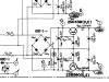
IIRC, the recommendation for capacitor multiplier circuits is to use capacitors (C608/609 in illustration) no larger than 470uF, otherwise the "speed of the circuit is compromised".

Capacitor multiplier.jpg
 
Really valuable information in this thread, thanks for that. Although it is safe to follow the lead of people with expertise and experience it's also nice to learn where there decisions are based upon.
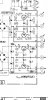
Do.i understand correctly, like for example the power supply for the driver board from the AU-919:

Screenshot_20220527-230006_Moon+ Reader.jpg

That capacitor C07-10 are the filter/storage capacitors and you can up the capacitance to a reasonable high value, space allowing, say 680-1000uF. But that C11-14, as part of the capacitance multiplier should be limited to 470uF and maybe even less.
 
...capacitor C07-10 are the filter/storage capacitors and you can up the capacitance to a reasonable high value, space allowing, say 680-1000uF. But that C11-14, as part of the capacitance multiplier should be limited to 470uF and maybe even less.

Yes, for this AK AU-919 Restoration, C07-C10 were increased to 680uF and C11-C14 were increased to 390uF.
 
If you do use a capacitor value which is too large, (for C11,12,13,14) it has the effect of slowing the 'power-on' 'rise' of the output of the supply - which could be undesirable for the circuits powered by its output.
 
Last edited:
Back
Top Bottom