• The move to the new server is done. There are some software and database maintenance updates in process. This has us passing the hat around to help out. We appreciate any donations. Seriously, even a dollar helps. The payment page may be found here - https://www.audiokarma.org/support.html

Working on a 2250B power supply, have a question

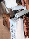
Just an update, I retested with DMM all the transistors again and will put back in before the weekend probably. While I was looking around the boards i noticed an emitter resistor that looked odd to me. This is on the bad board. 1 of the 4. It is measuring .1 out of circuit. Wondering if this is a clue? I poked around and measured a bunch of stuff from left side to right side. Just to see if anything jumped out, but it didn't. I was wondering though, some of these diodes on the bad board are reading in both directions. Not sure if that is normal?

So I think I will rebuild the bad board, take those measurements you mentioned in post 78.

After that, I really think I want to know if the other channel will work and I could disconnect both and probe the whole bottom of the board with easy access and see where this bad one starts to show the problems, but I am not sure if that would even help.

Open to any ideas. Thanks @dankik
 

Attachments

  • emmiter 2.jpg
    emmiter 2.jpg
    76.1 KB · Views: 4
  • emmiter 3.jpg
    emmiter 3.jpg
    97 KB · Views: 4
  • emmiter.jpg
    emmiter.jpg
    129.6 KB · Views: 4
It is measuring .1 out of circuit.
With that low of a resistance, you either need a good meter or you need to make two measurements.
  1. First connect the two test leads together and measure the resistance. If it's not 0, note what it is.
  2. Next, insert your resister to measure and note the value (in your case it was 0.1 Ohm).
  3. You will need to subtract the first measurement from the 2nd to get the true resistance because 0 is not 0.
  4. If it still measures 0.1, then get a new resistor
You never answered the question that I had on post #78 and #80.
You can measure continuity on the board with power off checking the resistance between the two points.
 
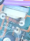
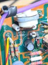
I am back, was starting to put some capacitors in tonight, and noticed some more damage I think! See the heat that the 150 ohm R736 has put on the R719 Trimmer, and the disintegrated R713?
 

Attachments

  • IMG_0498.jpg
    IMG_0498.jpg
    98 KB · Views: 13
  • IMG_0499.jpg
    IMG_0499.jpg
    154.1 KB · Views: 13
Good find. That component where R713 is looks more like a diode than a resistor. Can you tell if it is a diode?
At a minimum, those two components need to be replaced. Maybe the VR also, but we can test it with an Ohm meter.
  • On the schematic, R713 is shown as a 1k Ohm resistor.
  • Check the other P700 board to see what is installed there.
  • The burnt resistor, R736 should be a 470 Ohm resistor.
  • R737 on the schematic is shown as a 0 Ohm resistor (wire) but you have something installed there. Check the other board to see if they are the same.
 
Good find. That component where R713 is looks more like a diode than a resistor. Can you tell if it is a diode?
At a minimum, those two components need to be replaced. Maybe the VR also, but we can test it with an Ohm meter.
  • On the schematic, R713 is shown as a 1k Ohm resistor.
R713 WAS a resistor. the other board confirms that value if I remember right. The body of it is just gone and I have the other leg removed, see picture for the other side below and more info
  • The burnt resistor, R736 should be a 470 Ohm resistor.
Looking to see if I have a 470 around, if not I will reorder and replace on both.... I just measured both of these and they both measure 150 ohms and both have been hot. See pictures? Both the parts list and redrawn schematic list it as 470, maybe I need to test out of circuit?
  • R737 on the schematic is shown as a 0 Ohm resistor (wire) but you have something installed there. Check the other board to see if they are the same.
It is just a jumper wire with a ceramic cover on it.

RE Emmiters:
OK, so I did try to calibrate the ohmmeter setting, but it is just not accurate enough than to know that all for test .1ohms. I would like to replace them, but do not have any on hand it appears, and it also appears to be the best way to be sure they are within spec. I do have some .33, and I think emitter resistors usually range up to about .5 ohms. Not sure if a sub like that would be ok if I did it to both sides and properly adjusted bias.

In the 2 attached pictures, I finally see a previous repair I believe.

I think that on the "good" board these have been changed

C702 non matching cap
R713, it has no standoffs like the rest of the board
H701 again, no lead protection like the other side. This makes me want to check out all diodes, especially this one.
An area of solder with non cleaned up flux.

BTW, this project has been moved out of my office area and back into the garage where its over 100 degrees everyday. Hence some of the delays in reporting.

That's it for tonight. Thx!
 
Back
Top Bottom