

You are using an out of date browser. It may not display this or other websites correctly.
You should upgrade or use an alternative browser.
You should upgrade or use an alternative browser.
WTH is inside my AU-X111 MOS?
- Thread starter Hunleyj
- Start date

@Sansuiman - you can also have a look on these images, found them on the web. Hopefully they'll help, they are from the real thing

Regards
Regards
I'll probably open a new thread once I really get rolling on this. I'll check with you regarding any specific instructions on what you need, but gather high resolution photos of both the component and solder sides of the boards, close enough in size that the foil side can be overlaid to determine the circuit path between components will be useful in your effort.
Any news, anything available ?
My priorities will have to change at some point in the near future....and then I can't guarantee that I will still have the time for reverse-engineering.
Just letting you know, the choice is obviously yours.

@Sansuiman - sorry to hear that is a busy period for you, no pressure intended.
I promised to help and I'm just trying and willing to fulfill my commitment while I'm sure that I can.
Let's see then what we can come up with.
Just to mention - if it's not too complicated, you can try some photos also on PSU board and eventually control or tone amp (pre-amp) under the front of the amp (I guess it's located there, as usually is). Not necessary including the pcb traces on these boards, I'll try to figure out as much as I can from the components side. Having at least some guidelines on PSU and control-amp I think should help you later in your efforts to revive the amp.
Regards
I promised to help and I'm just trying and willing to fulfill my commitment while I'm sure that I can.
Let's see then what we can come up with.
Just to mention - if it's not too complicated, you can try some photos also on PSU board and eventually control or tone amp (pre-amp) under the front of the amp (I guess it's located there, as usually is). Not necessary including the pcb traces on these boards, I'll try to figure out as much as I can from the components side. Having at least some guidelines on PSU and control-amp I think should help you later in your efforts to revive the amp.
Regards
Guess who’s back? I was finally able to get an AU-X111 MV to arrive without broken glass (on third try). Of course the f*cker won’t power on and fails DBT, so I’ve got it open right now. @fojica, are you still looking for board pictures?@Sansuiman - sorry to hear that is a busy period for you, no pressure intended.
I promised to help and I'm just trying and willing to fulfill my commitment while I'm sure that I can.
Let's see then what we can come up with.
Just to mention - if it's not too complicated, you can try some photos also on PSU board and eventually control or tone amp (pre-amp) under the front of the amp (I guess it's located there, as usually is). Not necessary including the pcb traces on these boards, I'll try to figure out as much as I can from the components side. Having at least some guidelines on PSU and control-amp I think should help you later in your efforts to revive the amp.
Regards
Wellare you still looking for board pictures?
 maybe there's some light at the end of the tunnel after all with unicorn X-111MV
If you're willing to take some good shots....sure, I'll have a look

And I guess you want it up & running at the end the "tunnel".....right ?
P.S. don't sell this one eventually until the shots are get done by yourself - unfortunately it seems that "deals" around here are not necessary the most trustworthy things seen
Hey, yes I would love help getting this thing to power on after you’ve got what you need. My pal SansuiSteve helped me figure out how to isolate the power supply 5208 board, at which point the unit did power on, relay clicked, DBT passed. So I think we’ve ruled that out, but not sure what’s next. Anyway, I’ve attached a bunch of pictures of f-6070 amp board from different angles. I think this site will ruin them by dropping resolution though. Please let me know what kind of shots you are looking for.Well
If you're willing to take some good shots....sure, I'll have a look
And I guess you want it up & running at the end the "tunnel".....right ?
P.S. don't sell this one eventually until the shots are get done by yourself - unfortunately it seems that "deals" around here are not necessary the most trustworthy things seen
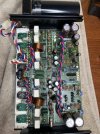
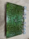
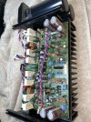
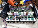
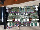
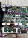
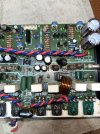

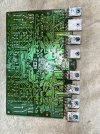
Last edited:
Hi, many thanks for the images.
Overall I can make a good idea on them as they are, but, if you have them in bigger size/resolution then it would be more helpful to have the "originals" uploaded somewhere, as the values of the components can be easier seen that way....or I can send you my email address, how it's more convenient for you.
Some shots with PSU board F-5208 from different angles (top side only, I imagine taking it out it's a bit complex) would also help to have a better idea.
Just in case you have the front taken off and you can see the flat-amp (or control-amp/tone controls) board, that would be also interesting. If not, no problem, maybe at some point later when recapping or adjusting. No hurry.
I'll try to help you with it, sometime soon my DIY EvoMOS Sansui should be completed and then I would have a bit of time to give you a hand.
My great and sincere appreciation that you are a man of his word
Regarding the problem that currently the amp has - I think you most likely have some output MOSFET's gone/shot.
Pinout as you look at them from the front is , left-to-right, G - D - S, aka Gate - Drain - Source.
You can try with an DMM set on resistances or diodes, then check between D and S for each of them....if you see "short"or near 0 (zero) ohms, then 99% that MOSFET is gone (or its brother in that pair or could be both of them broken, as they are parallel-ed in pairs of 2 (pairs of 2-Nch + pairs of 2 P-ch).
Let's see what you find on this check and then will see what comes next.
Hope this helps
Regards
Overall I can make a good idea on them as they are, but, if you have them in bigger size/resolution then it would be more helpful to have the "originals" uploaded somewhere, as the values of the components can be easier seen that way....or I can send you my email address, how it's more convenient for you.
Some shots with PSU board F-5208 from different angles (top side only, I imagine taking it out it's a bit complex) would also help to have a better idea.
Just in case you have the front taken off and you can see the flat-amp (or control-amp/tone controls) board, that would be also interesting. If not, no problem, maybe at some point later when recapping or adjusting. No hurry.
I'll try to help you with it, sometime soon my DIY EvoMOS Sansui should be completed and then I would have a bit of time to give you a hand.
My great and sincere appreciation that you are a man of his word
Regarding the problem that currently the amp has - I think you most likely have some output MOSFET's gone/shot.
Pinout as you look at them from the front is , left-to-right, G - D - S, aka Gate - Drain - Source.
You can try with an DMM set on resistances or diodes, then check between D and S for each of them....if you see "short"or near 0 (zero) ohms, then 99% that MOSFET is gone (or its brother in that pair or could be both of them broken, as they are parallel-ed in pairs of 2 (pairs of 2-Nch + pairs of 2 P-ch).
Let's see what you find on this check and then will see what comes next.
Hope this helps
Regards
Last edited:
@Hunleyj - for now it's pretty clear that the amp has a problem.
Your focus now should be to obtain an as-much-as-possible accurate assessment of the current status of the amp.
It worth keeping in mind that the problem could be related to one of the channels only or to both of them. You won't know for sure until you measure both.
I didn't see any cracking sign on the output MOSFETS in your pictures, so there is still a possibility that they may not be the problem themselves. Also, there are some visible numbers/markings written on them with black pen marker....maybe someone changed those recently for some reason ?
It also worth powering the amp as it is (power-amp modules NOT connected) and measure the DC offset at the connectors that go to power-amp input on both channels, in other words to see how much DC offset the pre-amp/flat-amp section is delivering to the power-amp. Ideally, there should be 0mV or, worst case, less than +/-3mV.
Do both checks that I mentioned (D-S on MOSFET's explained on previous post and the pre-amp DC offset) and let's see what your findings are.
P.S. which timezone are you in ?
Regards
Your focus now should be to obtain an as-much-as-possible accurate assessment of the current status of the amp.
It worth keeping in mind that the problem could be related to one of the channels only or to both of them. You won't know for sure until you measure both.
I didn't see any cracking sign on the output MOSFETS in your pictures, so there is still a possibility that they may not be the problem themselves. Also, there are some visible numbers/markings written on them with black pen marker....maybe someone changed those recently for some reason ?
It also worth powering the amp as it is (power-amp modules NOT connected) and measure the DC offset at the connectors that go to power-amp input on both channels, in other words to see how much DC offset the pre-amp/flat-amp section is delivering to the power-amp. Ideally, there should be 0mV or, worst case, less than +/-3mV.
Do both checks that I mentioned (D-S on MOSFET's explained on previous post and the pre-amp DC offset) and let's see what your findings are.
P.S. which timezone are you in ?
Regards
Hi, thank you for the advice! If you message me your email, I can send you higher-resolution picturesHi, many thanks for the images.
Overall I can make a good idea on them as they are, but, if you have them in bigger size/resolution then it would be more helpful to have the "originals" uploaded somewhere, as the values of the components can be easier seen that way....or I can send you my email address, how it's more convenient for you.
Some shots with PSU board F-5208 from different angles (top side only, I imagine taking it out it's a bit complex) would also help to have a better idea.
Just in case you have the front taken off and you can see the flat-amp (or control-amp/tone controls) board, that would be also interesting. If not, no problem, maybe at some point later when recapping or adjusting. No hurry.
I'll try to help you with it, sometime soon my DIY EvoMOS Sansui should be completed and then I would have a bit of time to give you a hand.
My great and sincere appreciation that you are a man of his word
Regarding the problem that currently the amp has - I think you most likely have some output MOSFET's gone/shot.
Pinout as you look at them from the front is , left-to-right, G - D - S, aka Gate - Drain - Source.
You can try with an DMM set on resistances or diodes, then check between D and S for each of them....if you see "short"or near 0 (zero) ohms, then 99% that MOSFET is gone (or its brother in that pair or could be both of them broken, as they are parallel-ed in pairs of 2 (pairs of 2-Nch + pairs of 2 P-ch).
Let's see what you find on this check and then will see what comes next.
Hope this helps
Regards

Got it! I’ll perform those tests and take the measurement in the next day or so. I’m in the MST time zone, so 1 hour later than PST here. Oh, do the MOSFET’s need to be out-of-circuit for those tests?@Hunleyj - for now it's pretty clear that the amp has a problem.
Your focus now should be to obtain an as-much-as-possible accurate assessment of the current status of the amp.
It worth keeping in mind that the problem could be related to one of the channels only or to both of them. You won't know for sure until you measure both.
I didn't see any cracking sign on the output MOSFETS in your pictures, so there is still a possibility that they may not be the problem themselves. Also, there are some visible numbers/markings written on them with black pen marker....maybe someone changed those recently for some reason ?
It also worth powering the amp as it is (power-amp modules NOT connected) and measure the DC offset at the connectors that go to power-amp input on both channels, in other words to see how much DC offset the pre-amp/flat-amp section is delivering to the power-amp. Ideally, there should be 0mV or, worst case, less than +/-3mV.
Do both checks that I mentioned (D-S on MOSFET's explained on previous post and the pre-amp DC offset) and let's see what your findings are.
P.S. which timezone are you in ?
Regards
For the D-S ohm-meter/diode check that I described, no.....not for now. I would have specified to take them out if it was required.do the MOSFET’s need to be out-of-circuit for those tests
This is just a quick/basic check
Depending on the result, you may have to take them out....but let's see the result first.
I'll send you a PM with my email address - many thanks again
Hi @fojica. I went and tested each one the MOSFETS as you described. The lowest resistance was about 64k ohms. Good news?Hi, many thanks for the images.
Overall I can make a good idea on them as they are, but, if you have them in bigger size/resolution then it would be more helpful to have the "originals" uploaded somewhere, as the values of the components can be easier seen that way....or I can send you my email address, how it's more convenient for you.
Some shots with PSU board F-5208 from different angles (top side only, I imagine taking it out it's a bit complex) would also help to have a better idea.
Just in case you have the front taken off and you can see the flat-amp (or control-amp/tone controls) board, that would be also interesting. If not, no problem, maybe at some point later when recapping or adjusting. No hurry.
I'll try to help you with it, sometime soon my DIY EvoMOS Sansui should be completed and then I would have a bit of time to give you a hand.
My great and sincere appreciation that you are a man of his word
Regarding the problem that currently the amp has - I think you most likely have some output MOSFET's gone/shot.
Pinout as you look at them from the front is , left-to-right, G - D - S, aka Gate - Drain - Source.
You can try with an DMM set on resistances or diodes, then check between D and S for each of them....if you see "short"or near 0 (zero) ohms, then 99% that MOSFET is gone (or its brother in that pair or could be both of them broken, as they are parallel-ed in pairs of 2 (pairs of 2-Nch + pairs of 2 P-ch).
Let's see what you find on this check and then will see what comes next.
Hope this helps
Regards
Don't forget to measure also on 200 mV scale the DC offset from the pre-amp (check on power amp input connectors with volume at maximum, power-amp modules NOT connected).
I have no idea what type of pre-amp X-111 MV has, so this is why a picture with the pre-amp board is very useful - to have an idea which signals should be present on power-amp inputs.
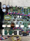
It would also be helpful to measure the voltages relative to GND/chassis - which are +/- voltages on power-amp connectors, both "drive" and "power" connectors. Just for the reference, the "drive" related connectors are yellow-encircled in the image below.
Also there's another thing - the bulb used for DBT in this case should be 100W minimum, given the idle power consumed by the amp normally (MOSFET outputs have about 2.5x times the bias of bipolar outputs in Sansui amps). In other words, if you used a 50W bulb it MAY BE sort of "normal" to look "lit" because amp is consuming some current in idle (with no input signal).
Hope this helps
I have no idea what type of pre-amp X-111 MV has, so this is why a picture with the pre-amp board is very useful - to have an idea which signals should be present on power-amp inputs.
It would also be helpful to measure the voltages relative to GND/chassis - which are +/- voltages on power-amp connectors, both "drive" and "power" connectors. Just for the reference, the "drive" related connectors are yellow-encircled in the image below.
Also there's another thing - the bulb used for DBT in this case should be 100W minimum, given the idle power consumed by the amp normally (MOSFET outputs have about 2.5x times the bias of bipolar outputs in Sansui amps). In other words, if you used a 50W bulb it MAY BE sort of "normal" to look "lit" because amp is consuming some current in idle (with no input signal).
Hope this helps
Attachments
I’m a little confused and want to clarify: Are the power-amp ”drive” connectors you circled the same as the “input connectors” you mentioned in the first sentence of your post? If that’s correct, then would I check across blue and red wires for step one (DC offset), and vs. ground for red, then blue for step two?Don't forget to measure also on 200 mV scale the DC offset from the pre-amp (check on power amp input connectors with volume at maximum, power-amp modules NOT connected).
I have no idea what type of pre-amp X-111 MV has, so this is why a picture with the pre-amp board is very useful - to have an idea which signals should be present on power-amp inputs.
It would also be helpful to measure the voltages relative to GND/chassis - which are +/- voltages on power-amp connectors, both "drive" and "power" connectors. Just for the reference, the "drive" related connectors are yellow-encircled in the image below.
Also there's another thing - the bulb used for DBT in this case should be 100W minimum, given the idle power consumed by the amp normally (MOSFET outputs have about 2.5x times the bias of bipolar outputs in Sansui amps). In other words, if you used a 50W bulb it MAY BE sort of "normal" to look "lit" because amp is consuming some current in idle (with no input signal).
Hope this helps

No, they are not the same and they have totally different functionI’m a little confused and want to clarify: Are the power-amp ”drive” connectors you circled the same as the “input connectors” you mentioned in the first sentence of your post? If that’s correct, then would I check across blue and red wires for step one (DC offset), and vs. ground for red, then blue for step two?
Drive yellow encircled connectors = power supply connectors for the "drive" section within the power-amp modules, meaning voltage +/-V. Red-Gnd = positive voltage, blue-gnd = negative voltage. Likely around +/- 30V or so.
Input connectors = signal connectors, those with 4 pins, with H (hot) and C (cold) markings on the external pins and located near the input double JFET, likely being uPA68H. That white connector in top-right corner in the picture with yellow-encircled power connectors for drive section. These are for low mV range and for checking DC offset, between (H)-gnd and (C)-gnd . (C) terminal may be put itself to gnd or not, depends on preamp topology (which I don't know how it is).
Clear now ?
Last edited:
Got it - thank you!No, they are not the same and they have totally different function
Drive yellow encircled connectors = power supply connectors for the "drive" section within the power-amp modules, meaning voltage +/-V. Red-Gnd = positive voltage, blue-gnd = negative voltage. Likely around +/- 30V or so.
Input connectors = signal connectors, those with 4 pins, with H (hot) and C (cold) markings on the external pins and located near the input double JFET, likely being uPA68H. That white connector in top-right corner in the picture with yellow-encircled power connectors for drive section. These are for low mV range and for checking DC offset, between (H)-gnd and (C)-gnd . (C) terminal may be put itself to gnd or not, depends on preamp topology (which I don't know how it is).
Clear now ?