• The move to the new server is done. There are some software and database maintenance updates in process. This has us passing the hat around to help out. We appreciate any donations. Seriously, even a dollar helps. The payment page may be found here - https://www.audiokarma.org/support.html

X-100-B tube matching help needed

klamsoss

Be willing to fail and try again.
I'll do a full write up this summer when my resto-mods are complete, but I need some help to get there.
A trusted tech in TX made my unit functional. The work was just fine, and I have really enjoyed the few hundred hours of listening, so far. So much so that I'm ready to take it to the next level.

Initially, I'm upgrading caps and trying to get the best matched quad from the dozen or so 7868s I have accumulated.
I've ordered k40y9 and k42y2 caps for the preamp, based on comments from many on AK, especially audiodon (R.I.P.).

I have installed 100R grid stability resistors and 10R cathode current sensing resistors. I followed Bruce and Dave's discussion of the cathod and stability resistor mods in this thread:
https://audiokarma.org/forums/index.php?threads/x-100-b-w-7868s.441082/#post-5656060

Bruce's "busses" have been replaced with "trunk lines" in my implementation. I ran a wire from the appropriate node and the resistors are floating connections (heat shrink covered) off of that. Sort of similar to (but much more messy than) the arrangement depicted in Dave's thread here:
https://www.audiokarma.org/forums/index.php?threads/kx-100-fishers-intro-stratakit.673654/

My issue is that I haven't been able to find a thread that explains the details of how to suss out the most closely matching 7868s, from a collection. I understand how to measure the current for each tube over the resistor, but the actual sequence of turning the amp on and off to switch tubes out... I know I'm measuring quiescent current, so no signal, but do I let it run for 20 min to warm up? Fully cool off after each tune is switched? Do I reset bias every time I change a tube out? Is there a reason to keep Sylvanias with only other Sylvanias and RCA with RCA? If someone can give me a procedure for it, that would be a big help to me.

Eventually I want to do IBAM and/or Dave's EFB, but I'm not an expert with this stuff yet, so, starting with baby steps.

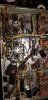
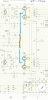
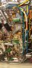
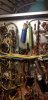
Photos 1 and 2 are the same pic, but one has my attempt to highlight my "trunk lines" and how I have them set up.
The blue sleeved trunk are the 10R cathode current sensing resistors. This trunk is connected to the nodes indicated by the schematic: pin 5 of V4, C4+ (100uF cathode cap), the cathode cap's parallel 560 ohm high watt resistor (I used a 10w wirewound), and R76, which is linked with the bias adjustment pot (these are traced in brown).
Similarly, the grid stability resistor trunk (yellow) links with the 2.5kR 10w (R72) and 40uF filter cap ( C2b) (red trace), and the 1kR (R73, orange trace).
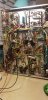
The third pic is the relevant portion of the schematic, with my color scheme noted on it.
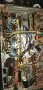
The last one is just a nice shot of my Fisher amp sitting next to my FM-100-B that I have restored with the help of the AK braintrust.

Thanks guys!
-Sam
 

Attachments
  • 20191229_104556.jpg
    20191229_104556.jpg
    66.1 KB · Views: 44
  • 20191227_233306.jpg
    20191227_233306.jpg
    63 KB · Views: 44
  • 20191229_222825.jpg
    20191229_222825.jpg
    32.1 KB · Views: 41
  • 20190826_083223.jpg
    20190826_083223.jpg
    48.1 KB · Views: 40
Last edited:
Register to hide this ad
Questions and Answers;
1. Matching is based on equal or near-equal quiesent current at a given Bias voltage. As the only bias adjustment for the X-100-B is a "GLOBAL" one, all tubes are going to react fairly much equally. For example you've got a quad in and a 40VDC bias,(after a 2-3minute warmup), the tubes measure 36ma-32ma-37ma-33ma. These are the only tubes you have. Swap #2 and #3, or #1 and #4, so you have 2 closely matched pairs. But you have multiple tubes. Split them into quads, and make yourself a spread sheet, then number all the tubes. With the 1st quad, set your voltage to 40V (after 3 minute warm up (incidently a tube is warmed up when it starts conducting and making sound(usually less than a minute), but lets let it stabilize a minute or 2). All you are doing with a 20 minute wait is contributing to the local Electric Co. CEO's bonus this year. Let the BSTD Starve like the rest of us...hehehe.

2.) Cycling the power off and on. Hot cycling is NOT RECOMMENDED. Hot cycling is cycling the power off and on or (on and off and on again) in less than a minute or 2. Give the tubes about 3 minutes minimum between power cycles to cool a bit. (Good time for a coffee break or even a Head/Latrine call.)

3.) Fully cooling between power cycles for tube swap is more to keep you from losing your fingerprints, but see #2 also. Wear a pair of light cotton gloves if you need to "HOT SWAP"(POWER OFF And it's STILL Somewhat hot or warm) a tube.

4.) YES BIAS must be determined and adjusted EVERYTIME you change out a tube as each one will have a different baseline current draw. You don't install sparkplugs in your car WITHOUT gapping them, even tho the factory does it and puts that cute little protective plastic sleeve over the end. No, you check the gap on every one to make sure they are in spec. Same with gapping a set of points on the distributor or ensuring the shutdown lever on a 6V71 Detroit works as designed. (Yeah, I'm old school...I think the xV71 Detroit 2 stroke Diesel engines series is/was one of the best truck Diesel engines out there (barring EPA, and all the Tree Huggers, but then I love a good running F-M 38-1/8D 10cylinder Submarine Engine thumping along at 720rpm making 1600hp. No leaks, no smoke, LOTS OF NOISE!!) Back to the questions.

5.) NO you don't have to keep Sylvie's with Sylvie's and RCA's with RCA's. Look for the manufacturers' EIA # on each tube (should be down by the pins on the side. RCA is 274, Sylvania is 312, Westinghouse is 337, Raytheon is 280. The tubes can be any of the 4 to start with as they bought other's tubes and remarked them a lot of times. If you have 4 closely matched Sylvies, Great. Same with RCA's. But they can be mixed and matched with no audible problems.
 
Larry, many thanks for your input!
I figured bias would be reset each time a tube was swapped but wanted to be sure. The distributor points gaping is a perfect analogy, too, especially given that I had my grand-dad's snap-on timing light out about a week ago (though I know next to nothing about the oil-burners, and exactly nothing about submarines).
SO,
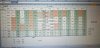
I've measured all the voltages for ALL of the pins for ALL of the tubes in the ENTIRE amp. See attached photo of the spreadsheet I developed to keep track of everything and auto-calculate current for each 7868 (if anyone else is working on a k/x-100 and would like the file for this spreadsheet, let me know. Happy to share!).

Initially, I was happy to see that my existing set (which were in it when my dad bought it, 2nd hand in 1970) are all darn close... 45ma, 52ma, 42ma, 44ma. BUT, I question how accurate these values are. I didn't get any nice, steady voltage readings on my DMM for the cathodes; instead, they kinda jumped around a bit, making it hard to be sure I had a "true" value. I recorded what I felt like was the "average", but the bias overall would ALSO drift, somewhat, over the course of several minutes. For example, if I set the bias to 40.00V, the "jumping" on the DMM would be +/- 0.05 V, but the "drift" would be as much as 0.4 V. Put the two together, and I'm not sure I can really rely on my numbers to actually match tubes well... I mean, the DMM jumping around would cover 10ma and the drift, even more...

Would an analog VTVM be better for this?
Or are the jumpy meter readings possibly indicative of other issues?
As you can see from my data table, the preamp tube voltages aren't picture perfect, either. Green shaded blocks are the voltages indicated in my service manual. Red highlighting indicates pairs of measured voltages that I think should match, but don't. Red text indicates the measured voltage was off by more than about 5%.
I do know my power supply is feeding the 100ohm screen stability resistors 360V rather than 365, but that shouldn't be that big of a deal...
 

Attachments

  • 20200101_182845.jpg
    20200101_182845.jpg
    77.2 KB · Views: 12
No signal. Nothing even hooked up to the inputs. Speakers only. Selector on "aux". All balance and tone controls set to middle/zero.
 
V7 = 18.35W (*)
V8 = 21.315W(*)
V9 = 17.04W (*)
V10=17.876W (*)

(*) Wattage after subtracting 3ma for screen dissipation from indicated ma.

Voltages shown on the spreadsheet are Mostly WELL WITHIN the 15% VOLTAGE Tolerances that Fisher specified when tested on a Line Voltage of 117VAC. The voltages on the schematic are "IDEAL" voltages with a line voltage of 117VAC. Voltages will vary due to individual component variances.


If you aren't using Mini Grabbers when testing suggest you do so. You'll get a more sable reading as the clamping effort on the wire or socket pin is steady, and you aren't in there shaking like a chihuahua crapping razor blades. Yes you can use a VTVM.

V1 & V2 swap out for another tubes and check voltages again. These two may be overly weak and not loading down.

An IBAM or IBBA would be pretty much Ideal for the increased dissipation on the 7868's. V8 is over dissipating even after accounting for the 3ma from the screen. The other 3 are running over 90%.
 
Larry, thanks again for the help.
I don't like worrying about the quality of my tools, so I use snap-ons for my car and I use a Fluke 87V DMM with pomona mini grabbers for anything electrical. I have two sets of the minis, and actually switched them out to be sure the jumpy readings weren't due to crappy connections within my equipment. I get reasonably stable DC readings everywhere other than the 7868 cathodes.
I also have a Heathkit IM-11, a classic VTVM. It's functional but I rarely use it because the Fluke serves my needs and I still haven't gone through the Heathkit since I picked it up at the swap. A refurb is on my to-do list, anyway, but if it might give me more stable or accurate readings, I'd knock it out sooner.

However, having re-read your (and others') comments on this X-100-B thread: https://audiokarma.org/forums/index.php?threads/how-to-set-bias-on-x100b.777653/page-2 it sounds like measuring the voltage from ground to the cathode buss, and then from ground to each cathode pin isn't the recommended way to calculate individual current. I should instead measure the voltages across each 10R directly, i.e. 1 grabber on my "trunk"/cathode buss and the other on each individual pin. I'll try that tonight and see if I get better readings. I'll also dial in 117 VAC on my autotransformer. I feel like the "drift" I saw might have been due to the somewhat variable wall voltage I have.
Eventually, I plan on doing an IBAM, but I think I need to learn a bit more before I take on that project. It'll require me to restuff the cans and eliminate the mess of power supply caps "under the hood", to make room.

As for the preamp tubes, I would be VERY surprised if V1 and V2 are weak. Unless I am remembering wrong, I have low-hours Sovtek 12ax7LPS bottles in there right now (matched pair bought new from viva tubes in late October). I really hope I'm remembering wrong, and I just forgot I switched the LPSs out. I'll check tonight. Regardless, I have several other pairs of 12ax7s I can swap, so I'll see what that does to things.
 
Okay, here's the report back after plugging in to my variac (which helped with the drifting, but not a lot), and measuring the voltage directly across the resistors (which did yield solid, stable voltage measurements).
Bias voltage: 40.2 V DC
Current
V7 - 45.5ma --> 18.29w
V8 - 54.1ma --> 21.75w (ouch!)
V9 - 46.4ma --> 18.65w
V10- 42.8ma --> 17.21w
so these are a dissipating a LOT of power, as a bunch, and one is a bit of a current hog. Still not confident that my numbers are super accurate, since the bias drifts between 39.95VDC and about 40.6VDC. I generally re-checked the bias between each current reading, but measuring the voltage between pin 3 and pin 9 is another story. I AM going to get that VTVM together just to have a continuous monitor on the bias when I do this stuff.

replaced V8 with another RCA labeled tube and got things to come more in line, (~18.9w, 20.1w, 19w and 17.5w) but still dissipating a lot of power. I'm going to go through the tubes I have and see if I can't bring things even closer in line.

One thing I noticed, that I didn't expect, was that the voltage at pin 3 was HIGHER than the voltage at the cathode buss for all tubes. I was under the impression that the voltage would drop between the buss and the tube due to the resistor...
 
Bias will drift a little. It's dynamic to an extent, even with no source, Volume off and other pots centered.

Swap V8 and V9 and see if the bias voltages even out a little more.

10 ohms isn't going to drop voltage appreciably. The resistor is only there for you to measure load. And in cases where a tube goes Chernobyl it'll blow like a fuse.

With Cathode Bias, the tubes wil run a bit hotter, (closer to max dissipation), than a fixed bias unit. I still think an IBBA would be best fix (or solution) for your tubes. But you have to balance the 12ax7 heaters against tube load. Right now your filament voltages are near the lower limits of good performance at about 10V. Any lower and distortion in the line amp sections will increase.

But lets see what Dave thinks about it.
 
Finally, after dozens of test runs over the last couple weeks, a good-to-excellent quad identified. :banana:
I've got plate dissipation of 17.6, 18.3, 18.4 and 18.6 watts with the bias at 40.2V. Running them pretty damn hard but under max rating, and just a 6% spread. I ended up with 2 sylvanias, one of the RCAs it had when I got it, and a "Wurlitzer by RCA" with a top vent so it makes me think it is actually a sylvania, bought by RCA, to sell to Wurlitzer. o_O
I also formed a 2nd quad that comes in at 18.3, 18.7 19.1 and 19.6 watts per plate. Still less than 10% spread but running 2 over their max rating. I'll save these for future use.

Is there a need and way to check gain match?
Related: How should I check the 12ax7s while they're in the amp? My mighty mite does emissions and grid leakage only. Is further testing even something I should worry about if pin voltages are within spec?

While matching 7868s, my PIO caps came. 500V k42y2 0.047uF and slightly big but reasonably priced 1000V k40y9 0.022uF. I had to get a little creative, especially on V6, but got them to fit. Clear shrink on the k40s (see pics). I bought in bulk (20 each) so cap pairs matched within 0.3% and all within 3% of spec value. (I have spares. Contact me if you're interested)
Deleted global LF filter per Prof. Gillespie's guidance (short 680pf in tone controls), replaced the 0.01 uF interstage coupling caps on the phono tubes, and swapped the hot-plate Sovtek 12ax7LPS, mentioned previously, for telefunkens that were in there when I got the amp from my dad. Plate voltages immediately dropped down to spec. I've started the RIAA circuit update (2.2M --> 10M on pins 7 in phono stage) but need to polish off the PEC delete/revise (parts came today). Then I'll post my full write up, complete with links to all the threads I used for reference, lots of photos, and examples of my data spreadsheets (which I am happy to share).

The first 4 or 5 hours was scary because while "detail" seemed improved, I felt like a lot of the "tube magic" was gone, somehow. Tone was dull, bass was weak, and it just sounded kinda lifeless. Things have improved notably with subsequent rounds of listening, though. I've got about 15 hours on it now, and the tone is mostly back, and there's definitely plenty of life in this thing. Sounding really good and continued improvement is expected with use. As a bonus, my work may also have resolved a L/R balance issue I was having, but the jury is still out on that. Looking forward to finishing up the revised phono EQ circuit and wrapping up work (for now).

Pics:
1. V3 through V6 from the bottom. The silver k40 on V6 is hiding under the green k42. Note that the 680pf ceramic caps in the tone controls are still in place in this shot. I shorted them with 24awg silver plated copper wire, subsequently.
2. OOPS! I somehow put the cathode cap in backwards, despite double checking. It blew up but no further damage that I could tell. ALL polar caps will now be installed with the orientation clearly visible so my post work/pre startup checks will catch something like this.
3. That's better! Also note the 10M on pin 7 of the phono tubes (V1 and V2) per Dave's guidance, as well as film replacements for the ceramic caps between pins 1 and 7 on those tubes.
 

Attachments

  • 1 20200119_013257.jpg
    1 20200119_013257.jpg
    63 KB · Views: 22
  • 2 20200119_001258.jpg
    2 20200119_001258.jpg
    49.7 KB · Views: 22
  • 3 20200119_013235.jpg
    3 20200119_013235.jpg
    56.1 KB · Views: 21
Cathode Bias will run them harder, but it's more flexible (in a sense) than fixed bias. At this point I don't see a need to do anything further to it, the spread is a little more than I like them, but with old stock tubes 6% isn't bad. Don't worry about gain matching, it's not worth the trouble, unless you can discern a 1db difference in level and have access to Dave's Custom Built Tube performance tester. But I don't think even that one will gain match. A CURVE TRACER Might, but finding someone with one and knowing how to use it correctly is harder than finding a full set of Hen's Teeth. If all the voltages are within 10-15% of nominal schematic readings @ 117VAC line voltage, close it up, Turn off the OCD meter, and enjoy the hell outta it.

Take out the 17.6 in the 1st quad and replace it with the 18.3 from the 2nd quad. replace 18.4 from 1st quad with 18.7 from 2nd quad

Your 1st quad in the X-100-B will be 18.3, 18.3, 18.6, 18.7. that'll tighten up the spread and give you an identical side and the other side 1ma spread. Ideally 3ma spread from low to high maximum. If feel the need to appease the OCD gods, see if you have another tube that draws 18.6. swap that in inplace of the 18.7. Otherwise you're good.
 
My Gm tester does in fact include a function to measure the AC Gain of small signal tubes -- and it's notable that AC Gain does in fact vary somewhat between otherwise nearly identical Gm reading tubes -- as much as 15%. This speaks to the larger issues of tube testing (there is no one test that is appropriate for all tubes) and the sound of different tubes (tubes don't have a sound -- only a circuit does; but let's face it, two 12AX7 tubes that have an indicated GOOD and matched Gm reading in all four sections, but one tube has 15% more AC Gain in its sections than the other tube does, will produce audibly and measurably different performance results in most classic phono preamp designs using active EQ, with one tube ultimately only producing (typically) 72% of the other tube's gain, or the other tube producing 138% more, take your pick). This is the reason that phono preamp tubes can be the most sensitive to tube selection, with brand selection having much less to do with the matter, other than a brand's general characteristics tendencies.

In non-EQ circuits (like line and driver stages for example), the effects of tube AC Gain variation between tubes are greatly minimized by the use of NFB, making it just one of the reasons that NFB is used in high quality sound reproduction equipment. But, differences (although smaller) can still be measured none the less.

Without test equipment specifically designed to measure a vacuum tube's AC Gain value, one way to approach at least determining the relative difference between various tubes of a given type would be to use one channel of an amplifier as a test bed. Use a cell phone (or other device) to inject a 500 Hz sine wave test signal into a high level input, and adjust the amplifier controls for a reasonable output output level. Connect your DVM (set for low voltage AC indications) across the speaker output and note the reading. In the line stage position for the channel being used, mark the tube installed there for the output level produced. Now, rotate other tubes into that position and note and mark their output level accordingly. Just make sure to not change out any tubes further down the signal chain during the test, which would amount to changing the test bed conditions. Those tubes can be certainly be tested, once other tubes are rotated into their positions, and the test bed basis reestablished again.

Dave
 
Larry, many thanks for your guidance through this process. I'll see how things match up swapping the suggested tubes, but my recollection was that tubes from quad "A" didn't play nicely with quad "B". As you know, swapping a single tube can shift the current pulled by the remaining 3. We'll see this weekend.

Dave, as usual, great insight! I'll input a couple different frequencies over the weekend and see what happens. I have a signal generator and oscilloscope, if that opens up other testing strategies, but the above method makes sense to me. Actually, it's a brilliantly simple way to get at the desired info!
 
Edited*
Just to clarify, in order to implement the gain measurement outlined above, I'd be using one of the the tone control/line preamp tubes (i.e. V3 and V4 in the X-100-B), and NOT using the phase inverter ( V5 and V6) or phono (V1 and V2) tube positions, correct?

As an addenda, I'm wondering if there is useful information to gain about the tubes or the amp itself from a similar test of preamp tubes in other positions? Apologies if this is a neophyte question, but, after all, I am a neophyte with this stuff, but eager to learn more.
 
Last edited:
From what i glean from Dave's post, you'd use either V3 or V4 position, do the test with that tube, mark it with results then rotate the other line stage, test, then rotate the phono tubes in.

To do the phase inverter tubes you'd have to swap the line stage and phase inverter tubes and reset the unit to the original parameters again as you've changed the down stream setup. Try for the exact value or as close to it as you can get it (volt meter reading). Then test the 2 phase inverter tubes one at a time.
 
Thanks, Larry.
Sorry, I didnt realize I'd either deleted some words or left them out and the 2nd part of my post made no sense. I've now edited it.

Basically, though, you guys just seem to have so many brilliant ways of gathering data, I was wondering if there is more to be learned while I have things set up to do the relative gain testing with V3 or V4.
Maybe there is not.
I'm just really enjoying learning all of this and know much of it will be useful when I tackle the eico ST70 I have in the wings (and to a lesser extent, my sister's marantz 1060). I'm open to any and all suggestions of what tests would be good for me to do (or just good to know how to do, for future reference).
 
Back
Top Bottom